
Feeder and perch

a technology of perch and feeder, applied in the field of feeder, can solve the problems of one size perch not necessarily fitting all, and the disadvantages of conventional feeders

Inactive Publication Date: 2008-11-13
EVANS GRAHAM CHARLES
View PDF20 Cites 19 Cited by
  • Summary
  • Abstract
  • Description
  • Claims
  • Application Information

AI Technical Summary

Benefits of technology

[0006]The inventor has realised that conventional feeders suffer from the disadvantage that one size of perch does not necessarily fit all. By providing a feeder for which the perch may be removably attached, one may for example replace one perch with another which may be more att...

Problems solved by technology

The inventor has realised that conventional feeders suffer from the disadvantage that one size of perch does not necessarily fit all.

Method used


Image

  • Feeder and perch
  • Feeder and perch

Examples


Embodiment Construction

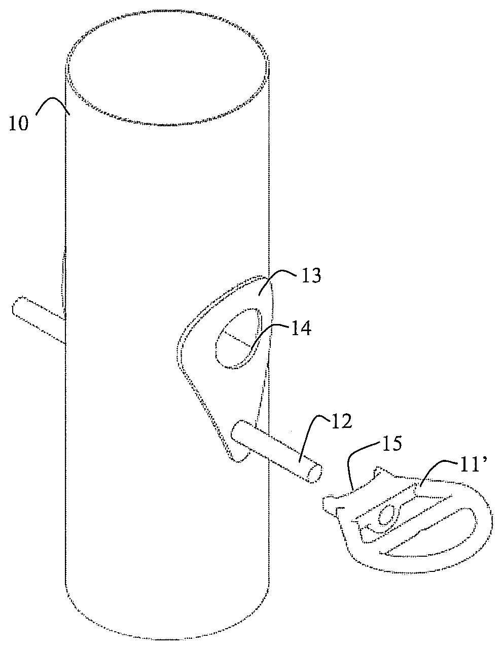
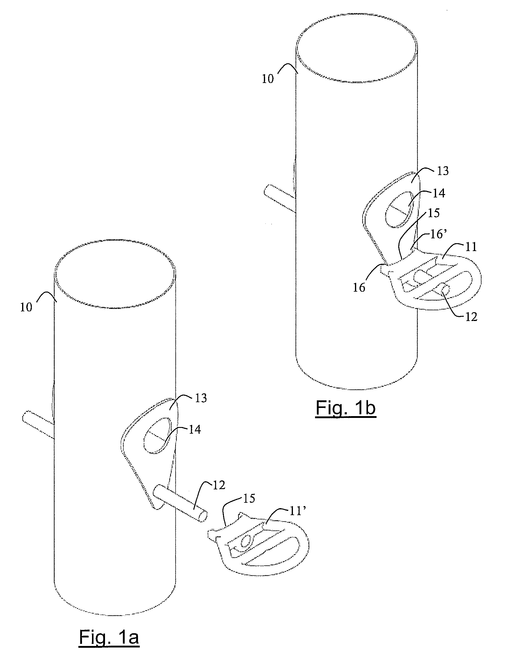
[0010]Referring to FIGS. 1a and 1b, a cylindrical bird feeder 10 is shown forming a receptacle for bird feed (not shown). The feeder supports a ring-type perch 11 on which a bird may land and feed. The perch is connected to and supported by the feeder using a post 12 which passes through the feeder, perpendicular to its cylindrical axis.

[0011]In FIG. 1a, the ring-type perch 11 is shown detached from the bird feeder 10. Whilst detached, the post 12 acts a perch.

[0012]In FIG. 1b, the ring-type perch 11 is shown attached to bird feeder 10, mounted on the post 12. The feeder has a reinforcement 13 attached to the cylindrical body of the feeder and which envelops a region around the feed hole 14 and the post 12.

[0013]The ring-type perch 11 is provided with a recess 15 which abuts with the reinforcement 13 at positions 16, 16′ either side of the reinforcement so as to prevent the perch from rotating about the post when the perch is fully engaged.


PUM


Abstract

A feeder is disclosed comprising a receptacle for feed, a post and a removable perch for an animal, especially a bird, to stand on; wherein the removable perch is removably attached to the feeder by engaging with the post during attachment.

Description

PRIORITY INFORMATION[0001]The present application claims priority to Great Britain Patent Application No. 0708830.5, filed on May 8, 2007, all of which is incorporated herein in its entirety.BACKGROUND OF THE INVENTION[0002]This invention relates to a feeder having a receptacle for feed and a perch for an animal (especially a bird) to stand on.[0003]Bird feeders are of course known and, at the time of writing, a large selection can be purchased from the following website: http: / / www.jacobijayne.co.uk.[0004]Known configurations of perch include posts and rings which are either permanently attached to or moulded integral with a feeder.SUMMARY OF INVENTION[0005]In accordance with the present invention, there is provided a feeder comprising a receptacle for feed, a post and a removable perch; wherein the removable perch is removably attached to the feeder by engaging with the post during attachment.[0006]The inventor has realised that conventional feeders suffer from the disadvantage th...

Claims


Application Information

Patent Timeline
IPC IPC(8): A01K39/012
CPCA01K31/12A01K39/012A01K39/01
Inventor EVANS, GRAHAM CHARLES
Owner EVANS GRAHAM CHARLES
Learn More