Optical fiber cables

a technology of optical fiber cables and fiber optic cables, applied in the direction of optics, fibre mechanical structures, instruments, etc., can solve the problems of poor fiber management, flat cables are prone to twisting and kinking, and unsatisfactory cable performan

Inactive Publication Date: 2008-11-20
FURAKAWA ELECTRIC NORTH AMERICA INC
View PDF30 Cites 23 Cited by
  • Summary
  • Abstract
  • Description
  • Claims
  • Application Information

AI Technical Summary

Benefits of technology

[0013]To address these problems, we propose a new cable structure for indoor installations comprising a dual-layer optical fiber buffer encasement of acrylate resin. The buffer encasement comprises a compliant acrylate inner layer that protects the fiber and minimizes stress transfer to the fiber, and a hard, tough acrylate outer layer that provides crush resistance. The dual-layer optical fiber buffer encasement is wrapped with a reinforcing layer and encased in an outer protective jacket. In preferred embodiments the dual-layer optical fiber buffer encasement has a dual reinforcing layer and a dual jacket.

Problems solved by technology

However, use of flat ribbons in cable may lead to undesirable cable performance in the field, e.g., difficult cable handling and routing in the field.
Flat cables are prone to twisting and kinking.
However, the round cable designs just described have several drawbacks:1. Poor fiber management.
This is a tedious process.
In addition, the fibers are free to twist, and change locations, when the cable is stretched, bent, etc.2. Poor fiber protection.
The fibers are prone to being damaged during the ribbonizing process.
In these cable designs there is little mechanical protection for the fibers when the cable is opened, and the operator must take extreme care to ensure no fibers are damaged when the aramid yarn is removed and the fibers are ordered one-by-one for ribbonizing.3. Poor crush protection.
These effects may result in high point attenuation and / or broken fibers, and limits the suitability of these cables for many indoor applications.
While these cables may be adequate for frame-to-frame interconnect applications, where they are installed in a relatively benign environment, they may not be sufficiently robust for installation in overhead or under-floor ladder racks, or raceways for room-to-room connections.

Method used


Image

  • Optical fiber cables
  • Optical fiber cables
  • Optical fiber cables

Examples


Embodiment Construction

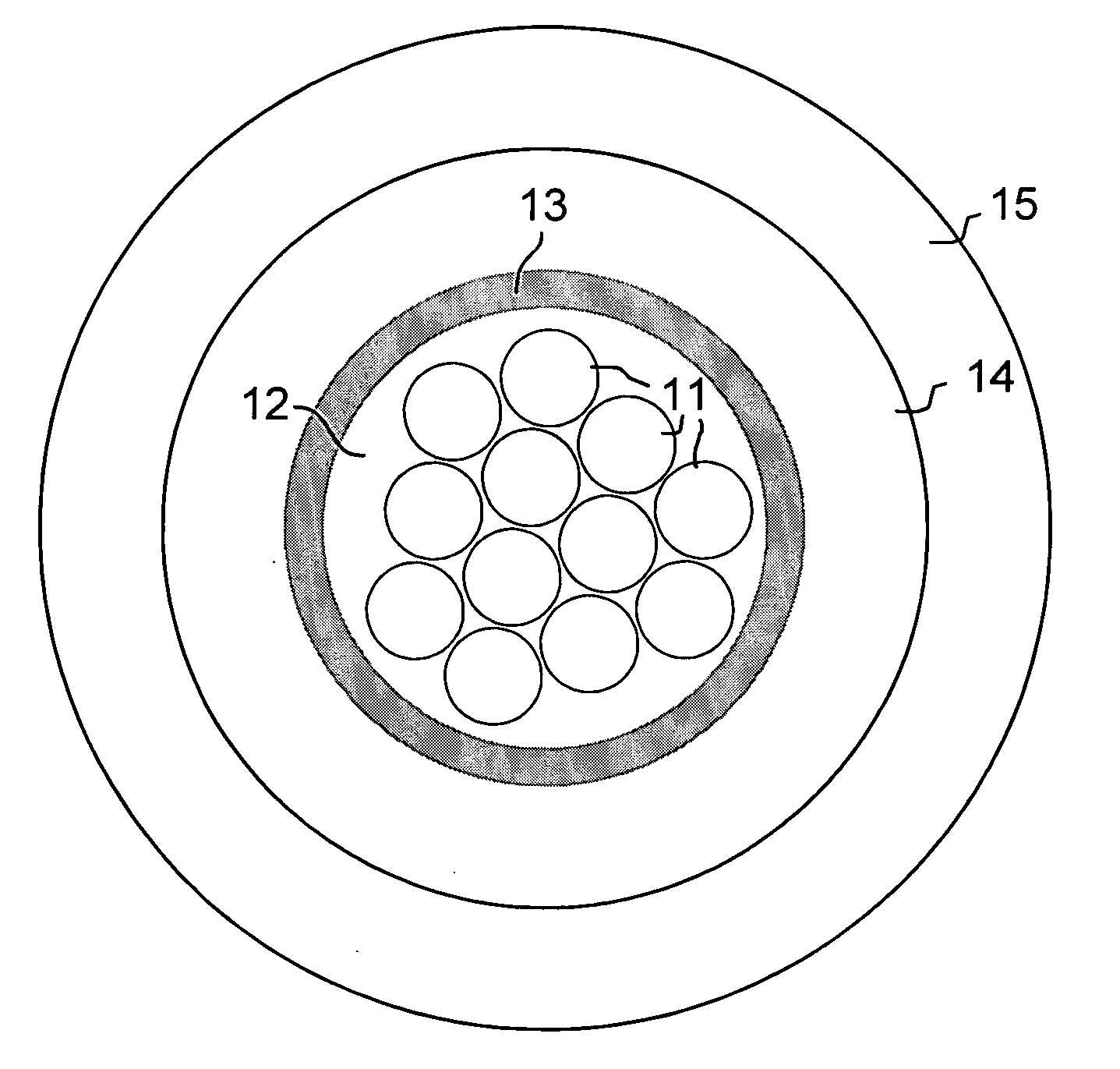
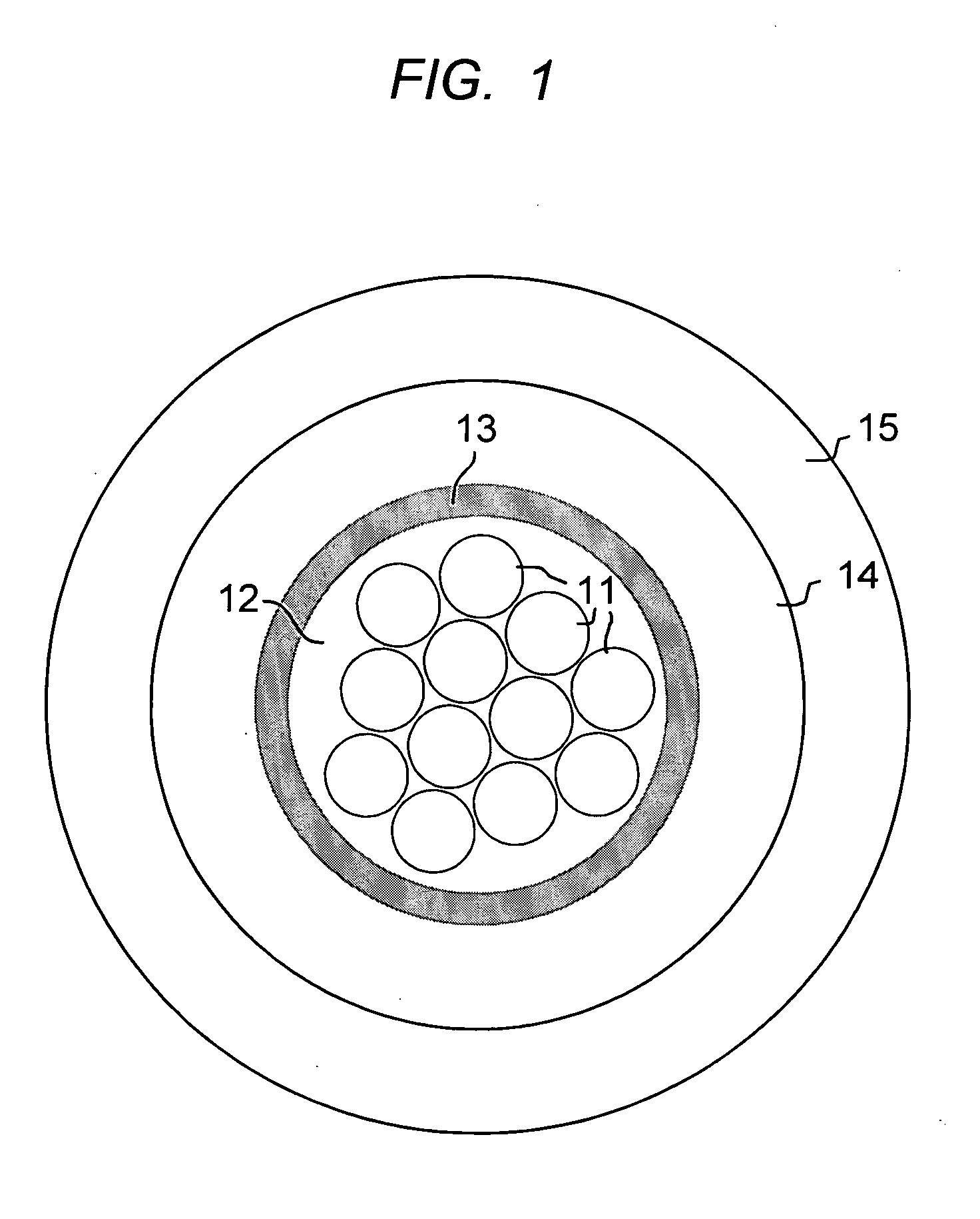
[0017]Referring to FIG. 1, a twelve fiber embodiment of the invention is shown with the twelve optical fibers 11, encased and embedded in a soft acrylate matrix 12. The elements in the figures are not drawn to scale. Surrounding and encasing the soft acrylate matrix is a relatively hard acrylate encasement layer 13. Together, the optical fibers, the acrylate matrix, and the acrylate encasement layer, comprise a round dual layer optical fiber buffer encasement. In this embodiment the optical fiber buffer encasement contains 12 optical fibers, but may contain from 2-24 optical fibers. Optical fiber buffer encasements with 4 to 12 optical fibers may be expected to be most common in commercial practice.

[0018]The dual-layer acrylate construction of the optical fiber buffer encasement, with the soft inner layer and hard outer layer, functions to minimize transfer of bending and crushing forces to the optical fibers, thus minimizing signal attenuation. Alternatively the optical fiber buffe...


PUM


Abstract

Described are new cable designs for indoor installations wherein the cable comprises a dual-layer optical fiber buffer encasement of acrylate resin. The buffer encasement has an acrylate compliant inner layer that protects the fiber and minimizes stress transfer to the fiber; and a hard, tough acrylate outer layer that provides crush resistance. The dual-layer optical fiber buffer encasement is wrapped with reinforcing yarn and encased in an outer protective jacket. A dual jacket embodiment adapted for indoor / outdoor installations is also described.

Description

RELATED APPLICATIONS[0001]This application is a continuation-in-part of U.S. application Ser. No. 11 / 903,779, filed Sep. 25, 2007, which claims the benefit of U.S. Provisional Application No. 60 / 917,953 filed May 15, 2007, incorporated by reference herein, and this application also claims the benefit of U.S. Provisional Application No. 60 / 975,830 filed Sep. 28, 2007, incorporated by reference herein.FIELD OF THE INVENTION[0002]This invention relates to optical fiber cables.BACKGROUND OF THE INVENTIONParts of this Background May or May Not Constitute Prior Art[0003]Conventional optical fiber cables for indoor use typically provide a convenient termination for standard single-fiber connectors, such as ST, SC or LC connectors, often using tight buffered optical fiber with an outer diameter of 900 microns. However, multifiber connectors are becoming increasingly popular in order to save space and installation labor. These connectors use multi-fiber “MT” ferrules. 12-fiber multifiber con...

Claims


Application Information

Patent Timeline
Patent Type & Authority Applications(United States)
IPC IPC(8): G02B6/44
CPCG02B6/4411G02B6/4432
Inventor GRAVESTON, MARK G.PEDDER, JASONWEIMANN, PETER A.
Owner FURAKAWA ELECTRIC NORTH AMERICA INC
Why Eureka
Try Eureka