Expandable corpectomy device

a technology of expandable vertebrae and implants, which is applied in the field of extendable vertebrae implants, can solve the problems of impaired fusion at the insertion site, difficult rotation of implants in situ, and failure to teach an expandable vertebrae, and achieve the effect of restoring the normal curvature of the spin

Inactive Publication Date: 2008-11-20
BIYANI ASHOK +2
View PDF17 Cites 86 Cited by
  • Summary
  • Abstract
  • Description
  • Claims
  • Application Information

AI Technical Summary

Benefits of technology

[0022]Yet another objective of the instant invention is to provide vertebra engageable endplates which may be constructed and arranged to accommodate various angular displacements of the cavity endpoints, and are effective to restore the normal curvature of the spine after the corpectomy device is installed.

Problems solved by technology

Although there are numerous patents directed to both artificial disk implants and expandable corpectomy devices, adapted for insertion and securement within the intervertebral space, the prior art nevertheless fails to teach an expandable corpectomy device which is capable of securely retaining bone growth / fusion materials therein, and which offers a means for simple incremental adjustment, such adjustment being conductible in situ, and thereby providing an individualized best fit, while providing a similarly adjustable and securable cover which, upon securement to the main body of the device, provides secure closure and retention of device engaging means effective for maintaining the device at a pre-selected degree of expansion.
Again, unlike the present invention, the design of this implant includes multiple slots which, in the extended position, fail to provide an internal cavity capable of preventing fusing material therein from leaking, thereby resulting in impaired fusion at the insertion site.
This construction is problematic in that rotation of the implant in situ is difficult.
Again, this type of construction is undesirable given that it requires in situ alignment of a plurality of parts in constrained and difficult circumstances.
This stress can eventually lead to cavitation of the device and possible damage to the vertebrae itself.

Method used


Image

  • Expandable corpectomy device
  • Expandable corpectomy device
  • Expandable corpectomy device

Examples


Embodiment Construction

[0045]Detailed embodiments of the instant invention are disclosed herein, however, it is to be understood that the disclosed embodiments are merely exemplary of the invention, which may be embodied in various forms. Therefore, specific functional and structural details disclosed herein are not to be interpreted as limiting, but merely as a basis for the claims and as a representation basis for teaching one skilled in the art to variously employ the present invention in virtually any appropriately detailed structure.

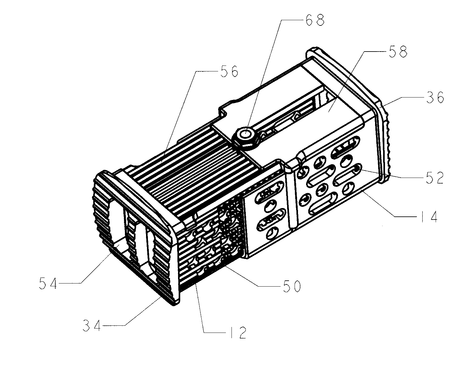
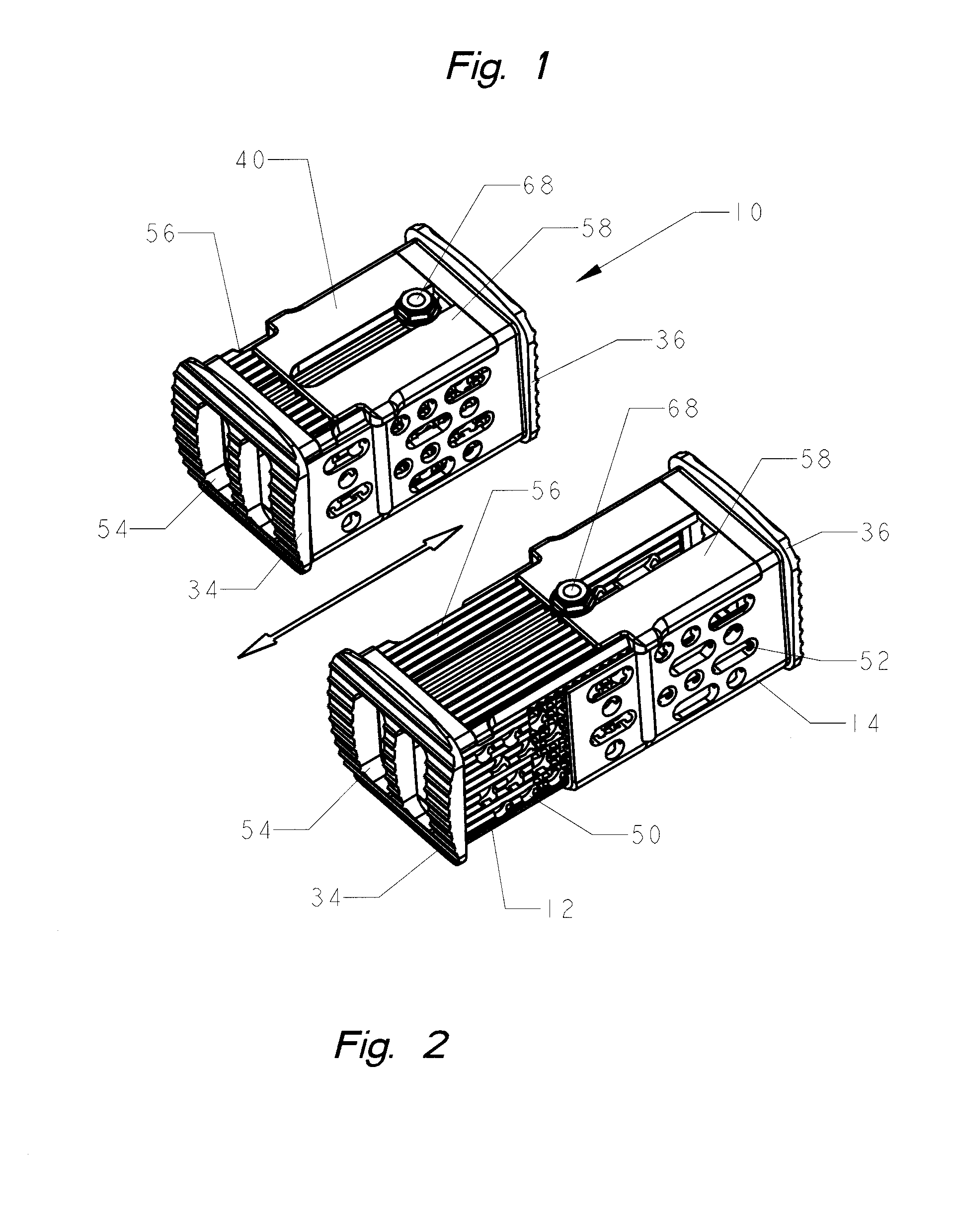
[0046]FIGS. 1 and 2 are upper perspective views of the fully assembled corpectomy device 10 (alternatively referred to as the implant device) in its minimum and maximum length condition, respectively. The instant invention could be used in all the spine levels (cervical, thoracic and lumbar).

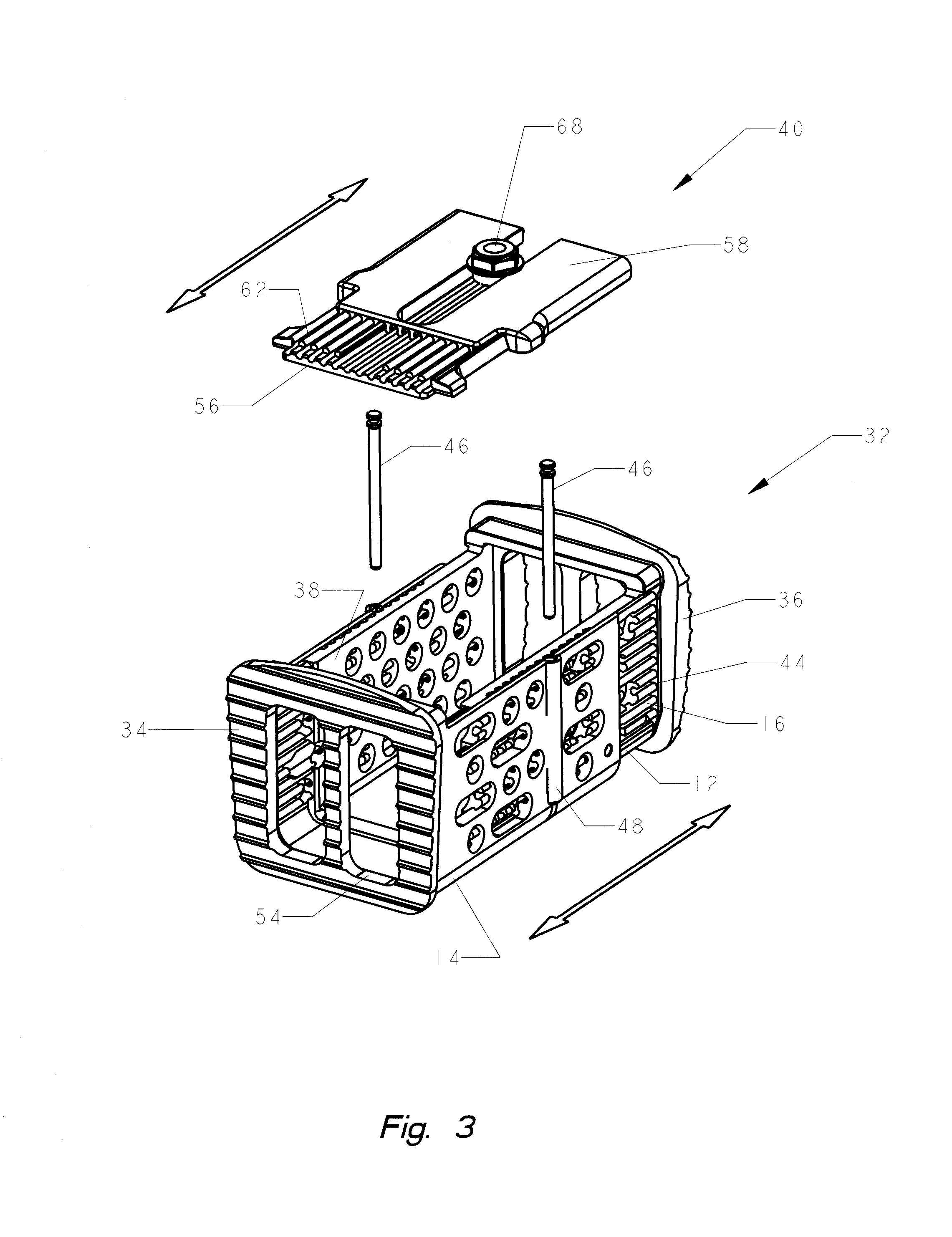
[0047]By way of an overview, the corpectomy implant device includes a base 32 formed by a first cavity defining member 12 telescopingly received in a second cavity defining member 14 ...


PUM


Abstract

The present invention describes an expandable vertebral implant and the method of use. The longitudinally expandable vertebral implant includes telescoping sections adapted for incremental expansion and ease of securement at any desired increment in situ, and constructed and arranged to engage opposing vertebrae, while simultaneously permitting easy insertion and removal of a similarly expandible top member.

Description

REFERENCE TO RELATED APPLICATIONS[0001]This application claims benefit of the filing date of Provisional Application No. 60 / 800,814, filed on May 16, 2006, the contents of which are herein incorporated by reference.FIELD OF THE INVENTION[0002]The invention generally relates to improvements in expandable vertebral implants and their methods of use; particularly, to a longitudinally expandable vertebral implant including telescoping sections configured for incremental expansion and ease of securement at any desired increment in situ, and constructed and arranged to engage opposing vertebrae, while simultaneously permitting easy insertion and removal of a similarly expandible top member.BACKGROUND OF THE INVENTION[0003]The spine is formed by a flexibly arranged column of vertebrae divided into three sections (cervical, thoracic and lumbar). The vertebrae are separated by small cartilaginous cushions identified as intervertebral discs. Chronic back problems often manifest themselves due...

Claims


Application Information

Patent Timeline
Patent Type & Authority Applications(United States)
IPC IPC(8): A61F2/44
CPCA61F2/30744A61F2/44A61F2/4455A61F2002/2835A61F2002/30369A61F2002/30398A61F2002/30451A61F2002/30492A61F2002/30512A61F2002/30514A61F2002/3055A61F2002/30601A61F2002/30785A61F2002/30841A61F2002/30879A61F2002/4475A61F2220/0025A61F2220/0033A61F2220/0058A61F2310/00017A61F2310/00023A61F2310/00161A61F2002/30507A61F2002/30593
Inventor BIYANI, ASHOKDOUBLER, ROBERT L.HAMMILL, SR., JOHN E.
Owner BIYANI ASHOK
Why Eureka
Try Eureka