Corpectomy device and methods of use thereof

a technology of corpectomy and scapula, which is applied in the field of appendix for treating spinal conditions, can solve problems such as back pain, leg pain, or other neurological disorders, and achieve the effects of improving the quality of li

Active Publication Date: 2017-03-23
K2M
View PDF1 Cites 6 Cited by
  • Summary
  • Abstract
  • Description
  • Claims
  • Application Information

AI Technical Summary

Benefits of technology

[0015]In still yet another embodiment, the second support assembly may include a second support and a second rotatable member rotatably secured in a passage of the first support. The second support may be rotatably coupled to the second rotatable member such that rotation of the second rotatable member causes axial displacement of the second support. The second support may include a protrusion portion operatively coupled with the first end plate. The protrusion portion of the second support may define a bore configured to receive a pin. The first end plate may define a slot configured to receive the pin such that axial displacement of the second support enables selective transition of the first end plate from the first angular orientation to the second angular orientation.

Problems solved by technology

However, when the vertebrae are misaligned or a constriction is formed in the spinal canal, nerves of the spinal cord may get compressed and may cause back pain, leg pain, or other neurological disorders.

Method used


Image

  • Corpectomy device and methods of use thereof
  • Corpectomy device and methods of use thereof
  • Corpectomy device and methods of use thereof

Examples


Embodiment Construction

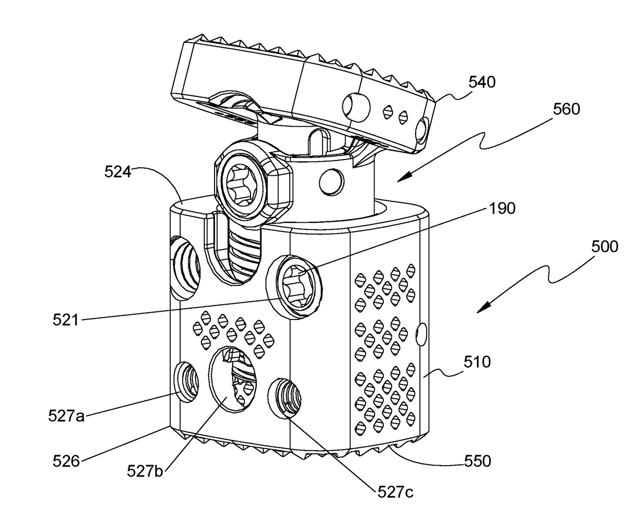
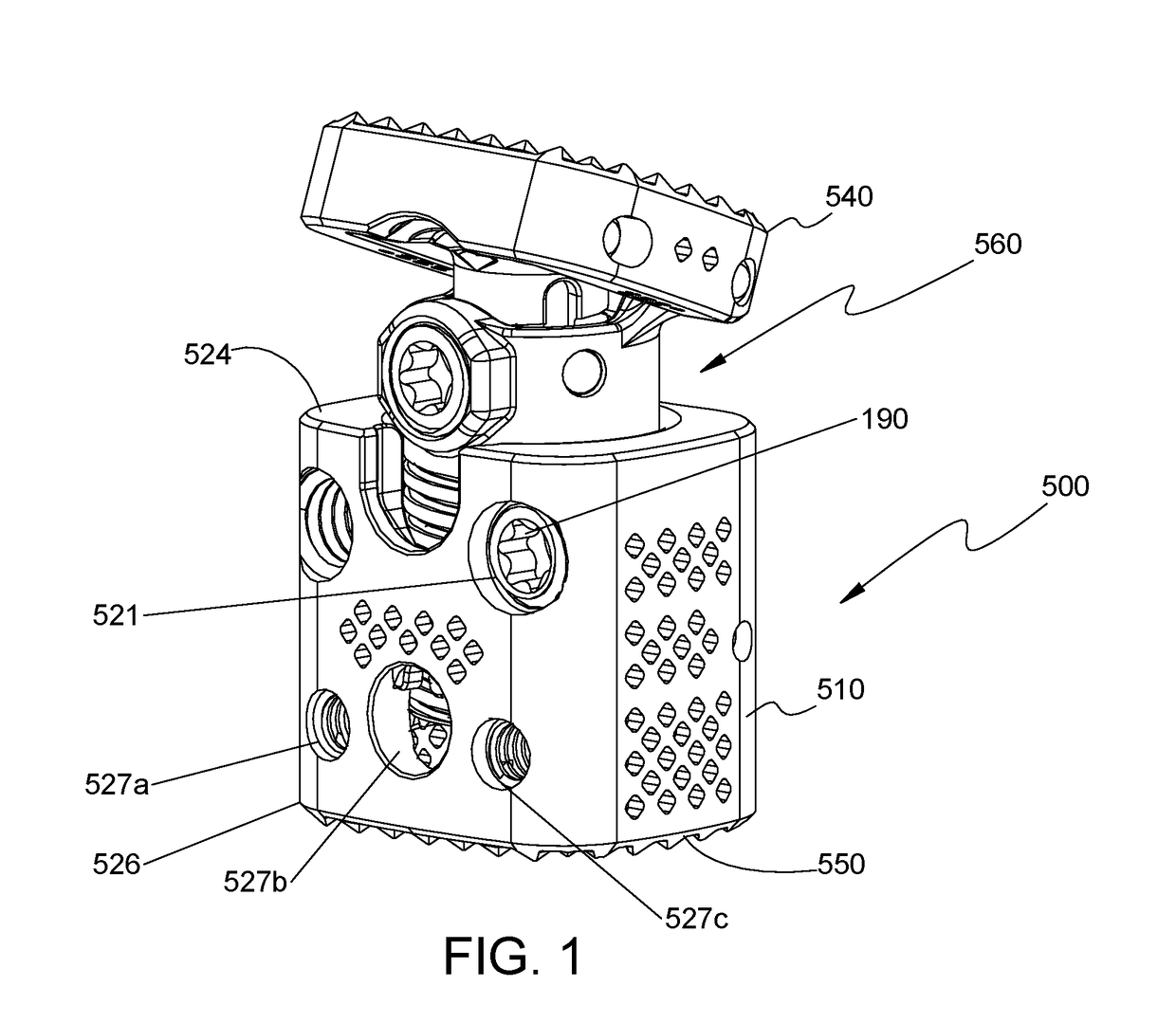
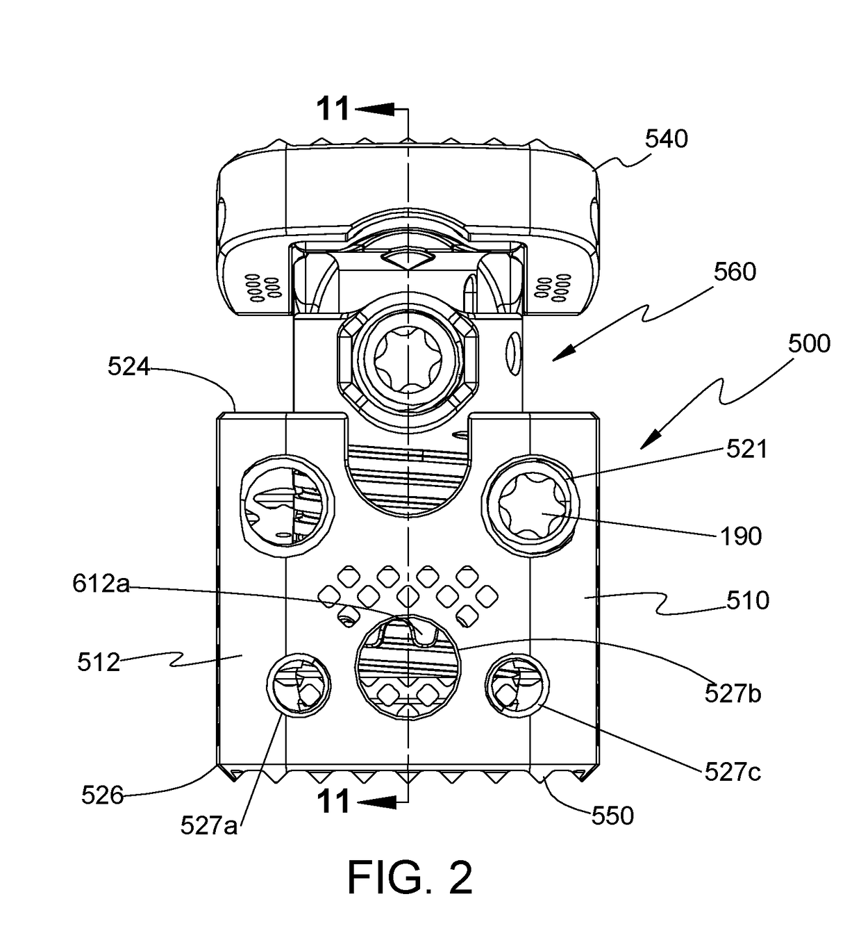
[0053]Particular embodiments of the present disclosure will be described herein with reference to the accompanying drawings. As shown in the drawings and as described throughout the following description, and as is traditional when referring to relative positioning on an object, the terms “proximal” and “trailing” may be employed interchangeably, and should be understood as referring to the portion of a structure that is closer to a clinician during proper use. The terms “distal” and “leading” may also be employed interchangeably, and should be understood as referring to the portion of a structure that is farther from the clinician during proper use. In addition, the term “cephalad” or “cranial” is used in this application to indicate a direction toward a patient's head, whereas the term “caudad” indicates a direction toward the patient's feet. Further still, the term “medial” indicates a direction toward the middle of the body of the patient, whilst the term “lateral” indicates a d...


PUM


Abstract

A spinal fixation device includes a housing defining a chamber and a longitudinal axis, and an end plate assembly operatively coupled with the housing. The end plate assembly includes a first end plate configured to engage a vertebral body and first and second support assemblies operatively coupled to the first end plate. The first support assembly is selectively movable between a first position in which the first end plate is spaced apart from the housing and a second position in which the first end plate is adjacent the housing. The second support assembly is transitionable between a first state in which the first end plate has a first angular orientation and a second state in which the first end plate has a second angular orientation.

Description

CROSS-REFERENCE TO RELATED APPLICATION[0001]This application claims priority to, and the benefit of, U.S. Provisional Patent Application Ser. No. 62 / 220,274, filed on Sep. 18, 2015, the entire contents of which is incorporated by reference herein.BACKGROUND[0002]Technical Field[0003]The present disclosure relates to an apparatus for treating spinal conditions, and more particularly, to an intervertebral implant.[0004]Background of Related Art[0005]The human spine includes thirty-three vertebrae. The vertebrae interlock with one another to form a spinal column. Each vertebra has a cylindrical bony body (vertebral body), two pedicles extending from the vertebral body, a lamina extending from the pedicles, two wing-like projections extending from the pedicles, a spinous process extending from the lamina, a pars interarticularis, two superior facets extending from the pedicles, and two inferior facets extending from the lamina. The vertebrae are separated and cushioned by thin pads of t...

Claims


Application Information

Patent Timeline
Patent Type & Authority Applications(United States)
IPC IPC(8): A61F2/44A61F2/46
CPCA61F2/4425A61F2002/4615A61F2/4611A61F2/4455A61F2/44A61F2002/30471A61F2002/30507A61F2002/30525A61F2002/30538A61F2002/3055A61F2002/30601A61F2002/4627A61F2002/4629
Inventor WALLENSTEIN, TODDBOYD, CLINT
Owner K2M
Why Eureka
Try Eureka