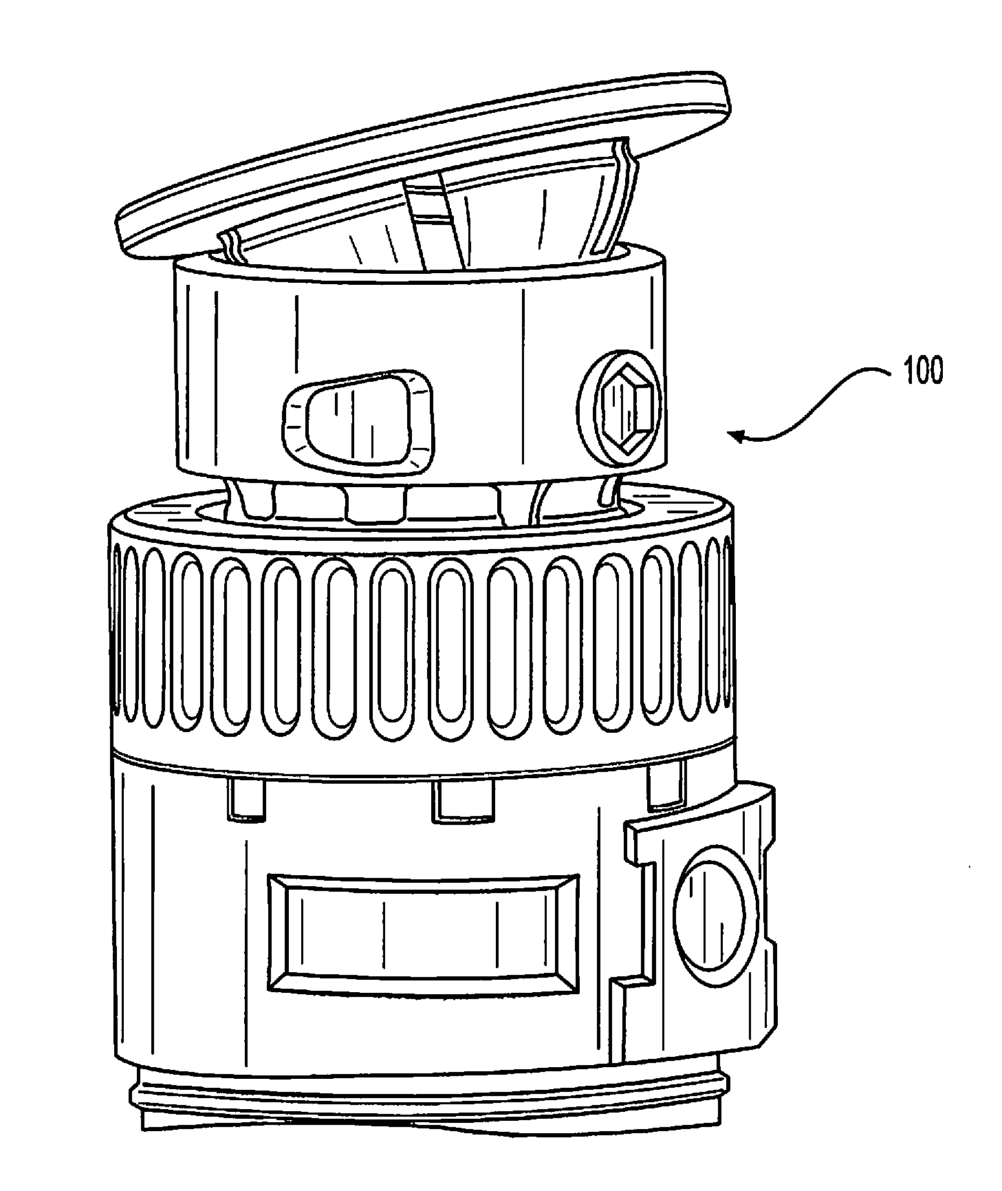
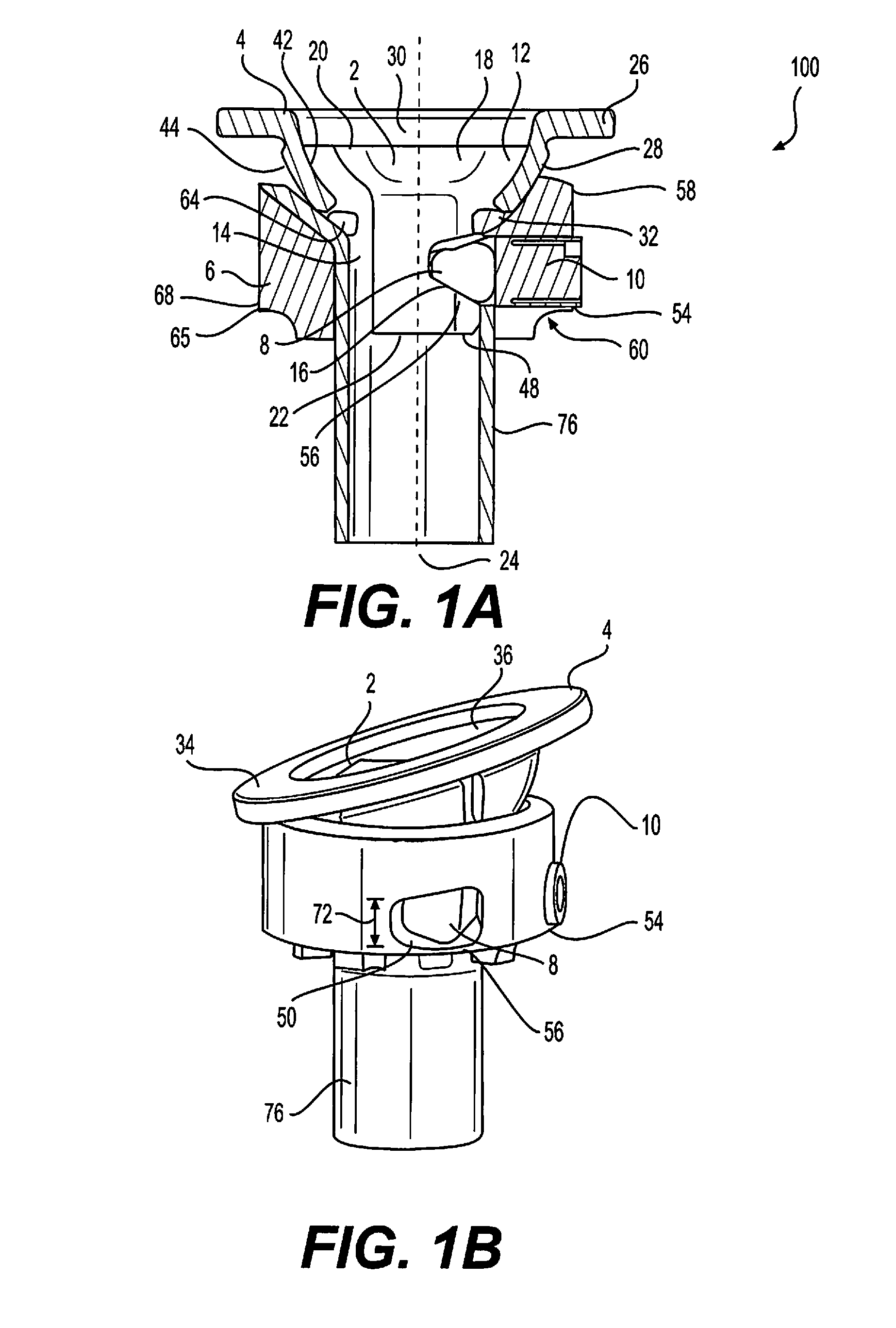
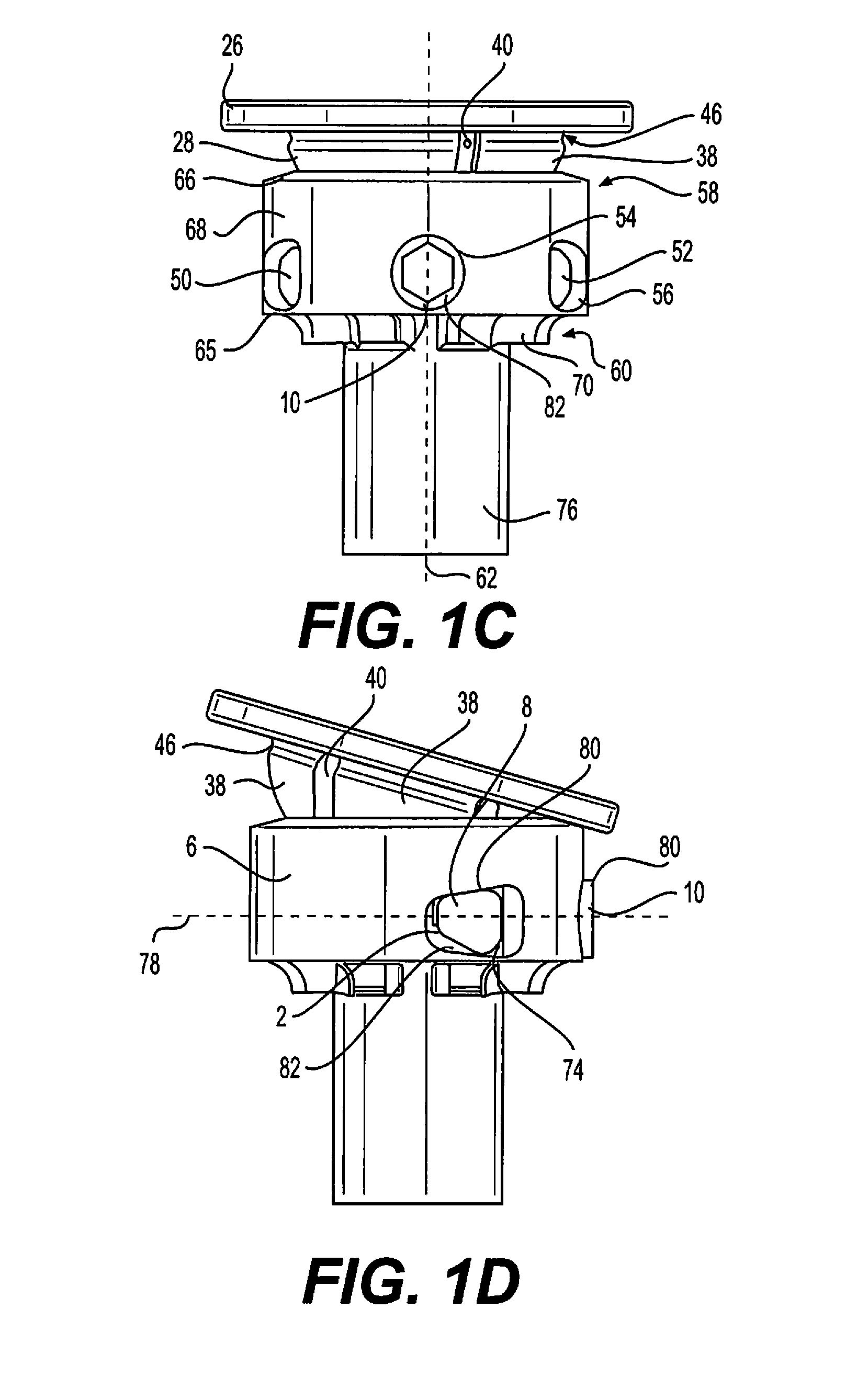
Vertebral implants and methods for installation thereof

a technology of vertebral implants and implants, which is applied in the field of vertebral implants and implant trials, can solve the problems of limiting the range of motion, injuring the nervous system within the spinal column, pain, numbness or weakness,

Active Publication Date: 2016-06-23
GLOBUS MEDICAL INC
View PDF5 Cites 7 Cited by
  • Summary
  • Abstract
  • Description
  • Claims
  • Application Information

AI Technical Summary

Problems solved by technology

Many types of spinal irregularities can cause pain, limit range of motion, or injure the nervous system within the spinal column.
These irregularities can result from, without limitation, trauma, tumor, disc degeneration, and disease.
In turn, the nerve compression can result in pain, numbness, or weakness.

Method used


Image

  • Vertebral implants and methods for installation thereof
  • Vertebral implants and methods for installation thereof
  • Vertebral implants and methods for installation thereof

Examples


Embodiment Construction

[0036]In a corpectomy procedure, a spinal canal can be expanded, and pressure on a compressed nerve can be relieved, by partially or completely removing one or more vertebral bodies adjacent to the compressed nerve. One or more intervertebral discs and other associated materials may also be removed. An implant (e.g., a cage, spacer, vertebral body replacement, or other prosthetic) may be inserted into the resulting cavity to subsequently stabilize the spine. In some instances, the implant can include an optionally-expandable body coupled to superior and inferior endplates that have been selected to match the contours of the vertebral cavity. Prior to insertion, a surgeon or other practitioner may approximate the appropriate size and lordotic or kyphotic angle of the endplates (e.g., via imaging and / or physical measurement devices such as a caliper or implant trial), select the endplates that most closely match the desired angles, and assemble the implant by connecting the selected e...


PUM


Abstract

Embodiments herein are generally directed to vertebral implants and implant trials for use with vertebral implant assemblies. In some embodiments, these implants and implant trials may be used in conjunction with corpectomy procedures.

Description

CROSS-REFERENCE TO RELATED APPLICATION[0001]The present application is a continuation of U.S. Ser. No. 14 / 580,273, filed Dec. 23, 2014, which is incorporated by reference in its entirety.FIELD OF THE INVENTION[0002]The present invention relates to vertebral implants, implant trials, and methods used to install these devices.BACKGROUND OF THE INVENTION[0003]Many types of spinal irregularities can cause pain, limit range of motion, or injure the nervous system within the spinal column. These irregularities can result from, without limitation, trauma, tumor, disc degeneration, and disease. One example of a spinal irregularity is spinal stenosis, the narrowing of a spinal canal, which can result in the compression of spinal nerves such as the spinal cord or cauda equina. In turn, the nerve compression can result in pain, numbness, or weakness. Spinal stenosis may be caused by one or more conditions such as development of bone spurs, thickening of ligaments, fractures, and disc degenerat...

Claims


Application Information

Patent Timeline
Patent Type & Authority Applications(United States)
IPC IPC(8): A61F2/44
CPCA61F2/4465A61F2002/4415A61F2002/443A61F2/4425A61F2/44A61F2/4611A61F2002/3008A61F2002/30235A61F2002/30383A61F2002/30405A61F2002/30433A61F2002/30515A61F2002/30517A61F2002/30538A61F2002/30556A61F2002/30565A61F2002/30523A61F2220/0041A61F2/4684A61F2002/30495A61F2/442A61F2/4455A61B17/8095A61F2002/30228A61F2002/30467
Inventor HOWARD, GEORGEHIMMELBERGER, JAMESGRAY, JASONMCLAUGHLIN, COLMHANSELL, NOAHWEIMAN, MARK
Owner GLOBUS MEDICAL INC
Why Eureka
Try Eureka