[0027]To explain the objects and advantages of the swimming pool cleaning vehicle in accordance with the invention, the following description of the drawing and the exemplary embodiments are provided in detail. As will be appreciated by those skilled in the art, the exemplary embodiments are provided to explain the swimming pool cleaning vehicle in accordance with the invention in detail and not to be used to limit its scope.
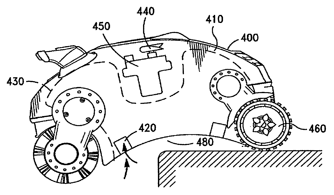
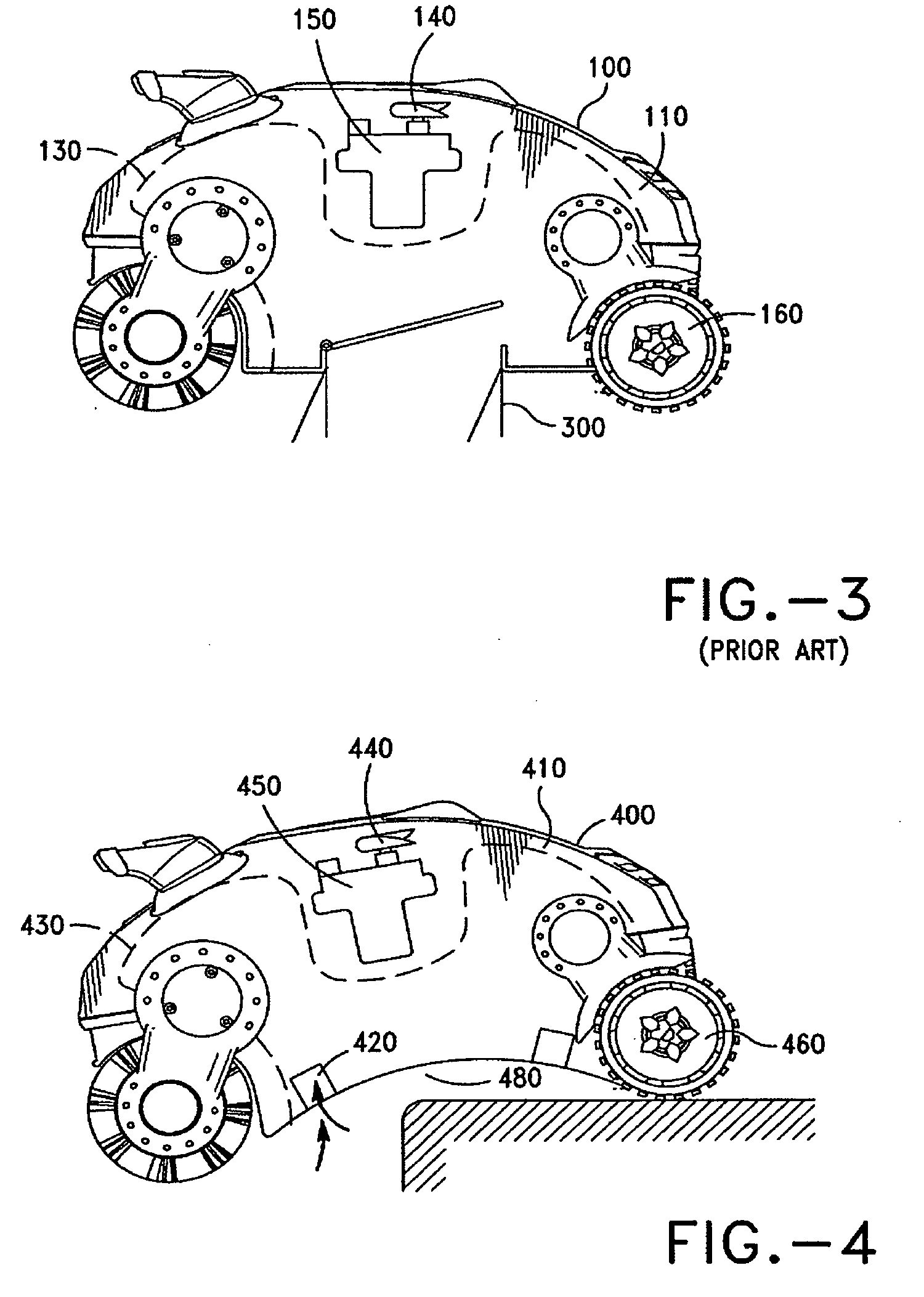
[0028]The swimming pool cleaning vehicle in accordance with the invention improves the art by providing a swimming pool cleaner with concave bottom to ensure the vehicle can easily overcome obstacles found on the pool surface. Additionally, by locating the water intake port adjacent to the vehicle's drive means, either using wheels and/or rollers water with dirt and debris is most likely to be sucked into the swimming pool cleaner interior and filtered.
[0029]FIG. 4 illustrates the construction of the swimming pool cleaning vehicle in accordance with the invention in a first exemplary embodiment. The first embodiment includes: an outer shell (400) having a hollow interior (410). Additionally, one or more water intake ports (420) are provided on the outer shell (400). A filtering mechanism including one or more filter bags (430) are provided inside the hollow interior (410) or in another emobodiement on the outer shell (400) for filtering water from water intake ports (420) and the filter mechanism traps the debris.
[0030]One or more water outlet ports (440) are provided on the outer shell (400). The vehicle includes a water pump mechanism including one or more water pumps (450) placed under the corresponding water outlet port (440) for pumping water from outer shell (400) to outside pool water.
[0031]The drive mechanism of the swimming pool cleaning vehicle in accordance with the invention includes a certain number of wheels and/or rollers and various combination thereof. The wheels and/or rollers (460) (this disclosure assigns 460 on both wheels and rollers) are located adjacent the bottom (480) of the outer shell (400).
[0032]If only wheels (460) are provided, the wheel (460) will comprise 2 pairs located on the bottom (480) of the outer shell. Quite clearly to those skilled in the art, it is clear that 3 or more pairs of wheels (460) could be located on the bottom (480) in another exemplary embodiment.
[0033]If only rollers (460) are provided, the roller (460) will be generally 2 members, each member located on the ends of bottom (480) of the outer shell (400). Quite clearly to those skilled in the art, 3 or more rollers (460) could be located on the bottom (480) in another exemplary embodiment.
[0034]If a combination of wheels and rollers (460) are provided, normally one pair of wheels and 1 roller member will be located oneach end of bottom(480). Quite clearly to those skilled in the art, more pairs of wheels and rollers (460) could be placed at the bottom(480) of the outer shell (400) an another exemplary embodiment.
[0035]The wheels and/or rollers (460) are driven by motor placed inside or outside the outer shell (400). The pairs of wheels and/or rollers (460) can also be hydraulically propelled e.g. via water jet via pressurized water generated by water pump placed inside or outside the outer shell (400). (Not shown in the illustration).
[0036]In the exemplary embodiment shown here he swimming pool cleaning vehicle in accordance with the invention runs around the pool surface without being affected by floor obstacles. The 480 is concaved inwardly toward the hollow interior. This allows the swimming pool cleaner easily overcome swimming pool floor obstacles such as the main drain cover or even steps.
[0037]In various exemplary embodiments, the bottom (480) is symmetrically concave or asymmetrically concave. In one exemplary embodiment the bottom (480) has two drive members. In one embodiment, the drive mechanism includes two pairs of wheels (460). In another exemplary embodiment there are two roller members (460). In thiis embodiment, the bottom (480) is a front to back symmetrical while being concaved inwardly either between front wheel and rear wheel, or between front roller and rear roller. If more than 3 pairs of wheel or 3 rollers are used, the body shell (400) bottom (480) is symmetrical front to back and concaved inwardly between adjacent wheels or rollers. Furthermore, amount of the bottom being concave inwardly can be increased to accommodate greater swimming pool floor obstacles.
[0038]Since the bottom (480) is concaved inwardly, most of the bottom (480) has a high floor clearance. In order to ensure water intake port (420) will suck in water with dirt and debristhe intake port is located adjacent to the the drive mechanism, namely the wheels and/or rollers or combinations thereof. It will be appreciated that during operation of the swimming pool cleaning vehicle in accordance with the invention, the floor clearance remains unchanged.
[0039]In the above exemplary embodiment, the water intake port (420) is located on the bottom (480) and closely adjacent to the drive mechanism. Also, as will be appreciated to those skilled in the art, the required partial vacuum and water flow at the water intake port (420) remains effective so that dirt and debris are easily sucked up into the swimming pool cleaning vehicle in accordance with the invention.
[0040]In one exemplary embodiment, the water intake port (420) points downwards. In another exemplary embodiment, the water intake port (420) is located closely adjacent to the drive mechanism.
[0041]It will be appreciated that the number of water intake ports (420) in other exemplary embodiments varies according to the cleaning needs. Additional water intake ports are provided as needed.
[0042]Another exemplary embodiment of the swimming pool cleaning vehicle in accordance with the invention is illustrated in FIG. 5. In this exemplary embodiment the bottom (480) is asymmetrically concaved inwardly. The bottom (480) includes a variety of wheel and roller (460) combinations the bottom (480) is asymmetrically concaved inwardly between front roller and rear wheel. In another exemplary embodiment, the bottom is asymmetrically concaved inwardly between the front and rear drive mechanisms. The asymmetricly concaved bottom is defined by more than one curved surface. The water intake port (420) is located on the bottom (480), and located adjacent the drive mechanism.
[0043]Another exemplary embodiment of the swimming pool cleaning vehicle in accordance with the invention is illustrated in FIG. 6. In this exemplary embodiment, the water intake port (420) is located on the bottom (480) and directly under the drive mechanism.
[0044]This location has the lowest clearance between vehicle and swimming pool floor. The water intake port (42) here allows the dirt and debris to be sucked up into the vehicle easily. In this exemplary embodiment the water intake port (420) opening points downward toward the pool surface, while in operation
[0045]In conclusion, the swimming pool cleaning vehicle in accordance with the invention includes the vehicle having a concaved bottom for overcoming swimming pool floor obstacles as it runs along the swimming pool surface.
[0046]While the foregoing detailed description has described several embodiments of the pool cleaning vehicle in accordance with this invention, it is to be understood that the above description is illustrative only and not limiting of the disclosed invention. It will be appreciated there are also various modifications to the vehicle that are suitable for use in the exemplary embodiments discussed above and that there are numerous embodiments that are not mentioned but within the scope and spirit of this invention. Thus, the invention is to be limited only by the claims as set forth below.