
Respiratory face mask and headstrap assembly

Active Publication Date: 2008-12-04
NASHED RAMSES
View PDF19 Cites 34 Cited by
  • Summary
  • Abstract
  • Description
  • Claims
  • Application Information

AI Technical Summary

Benefits of technology

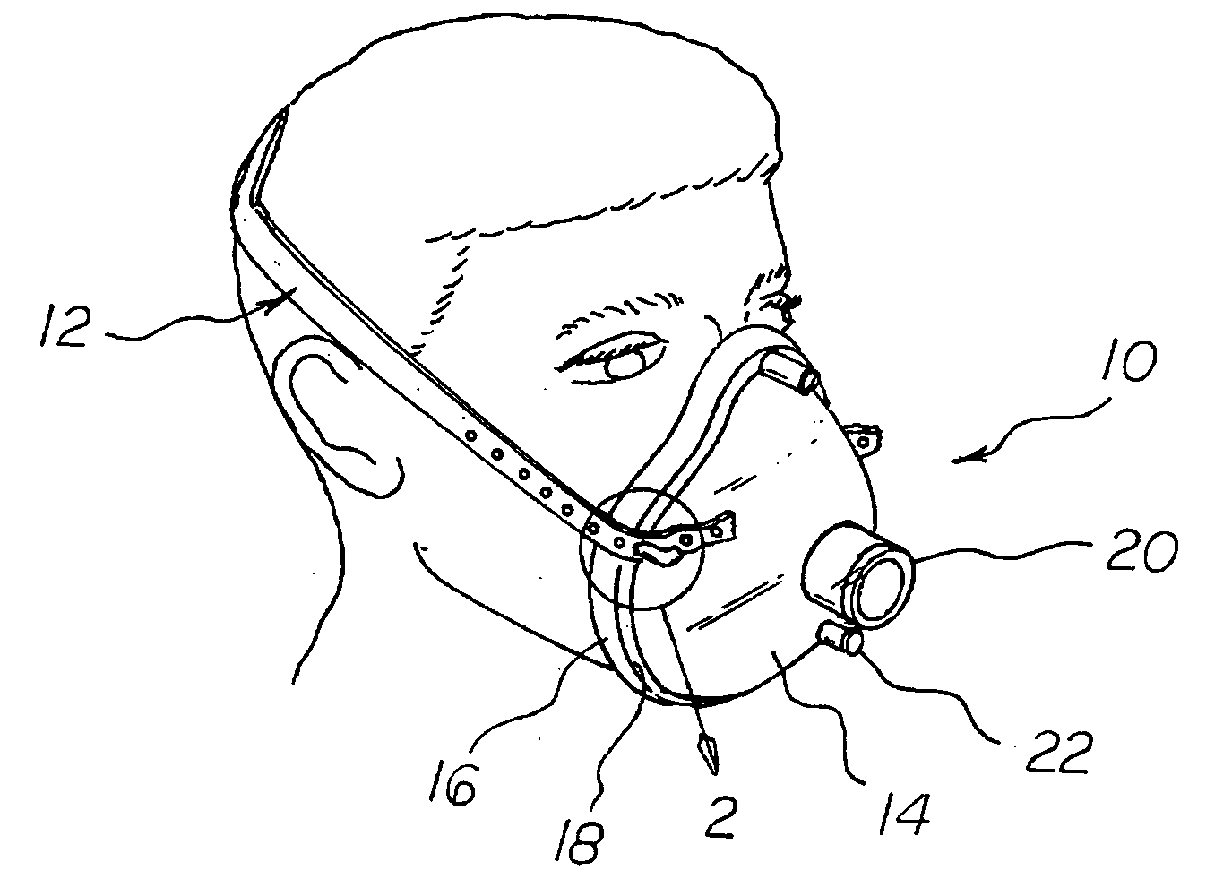
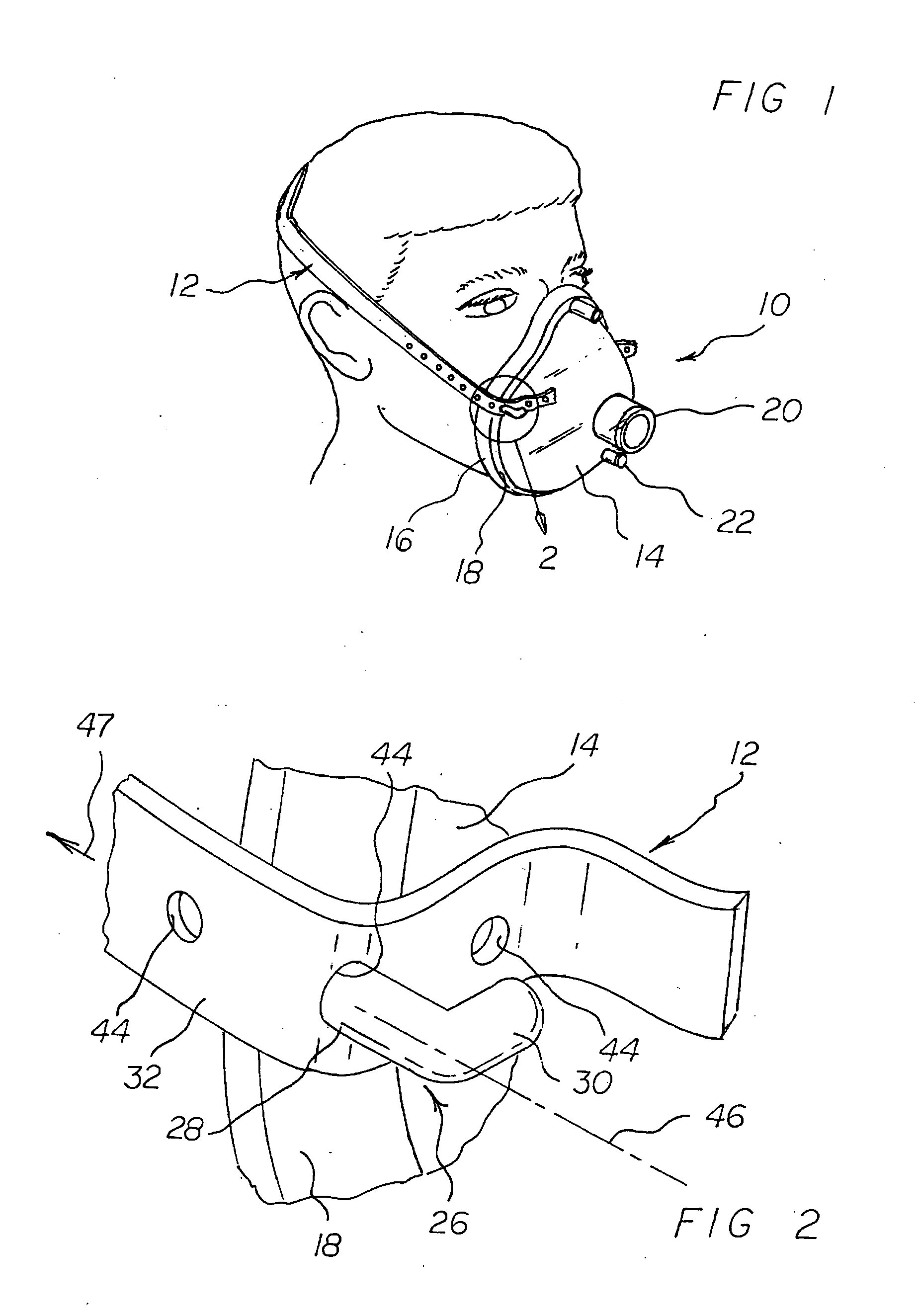
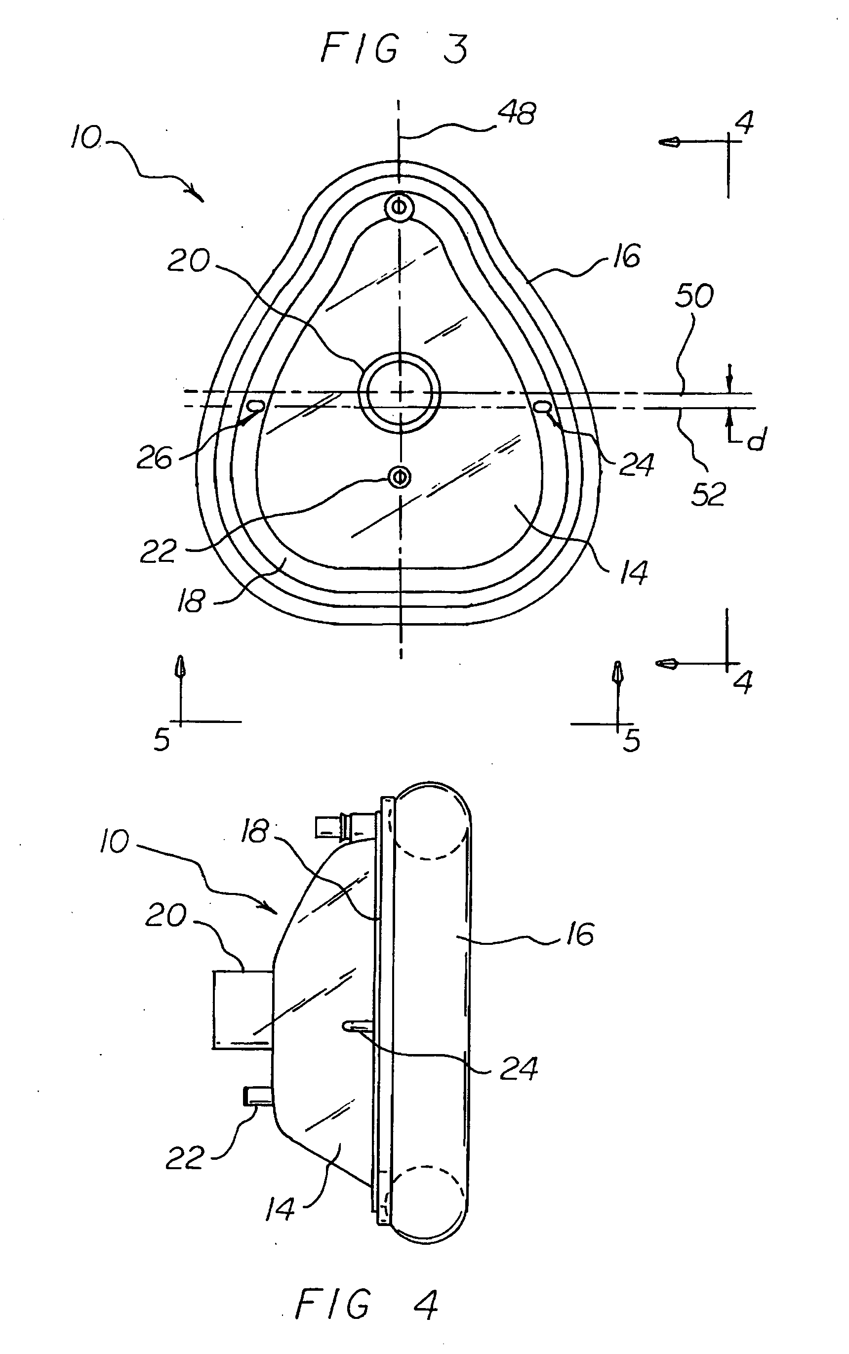
[0011]The present invention, briefly described, essentially comprises the anesthesia face mask of my prior application improved by the addition of a uniquely different headstrap attachment system and headstrap configuration. Rather than the simple strap disclosed in my prior application, the new headstrap disclosed herein comprises an annular shaped pressure-distributing central portion and a pair of arm extension portions extending laterally and oppositely from the central portion. Each arm extension portion includes a series of longitudinally spaced mask-engagement openings or perforations for providing a range of adjustment for different sized patients. Projecting upwardly on the peripheral edge or rim of the mask's body shell or member is a pair of substantially diametrically opposed riser posts for engaging corresponding ends of the strap arm extension portions through a corresponding one of the mask engagement openings in each arm extension portion end portion, respectively. When so engaged, the tension in the headstrap, and in each headstrap arm extension end portion particularly, is directed oppositely to the direction of extent of the corresponding riser post to which it is removably connected, thus providing a surprisingly simple, yet secure strap-to-mask attachment arrangement.

Problems solved by technology

Attempts have been made to affix such prior masks to the patient's head and face, but in so doing relatively bulky and cumbersome strap assemblies must be used.
These prior strap assemblies, in turn, require relatively excessive pressure to maintain mask stability because of the limited footprint of the mask's pneumatic sealing cushion.
Additionally, the attachment headstrap lugs have a T-bar distal end which is relatively difficult to mold and presents the possibility of snagging foreign objects in the surgical environment.

Method used


Image

  • Respiratory face mask and headstrap assembly
  • Respiratory face mask and headstrap assembly
  • Respiratory face mask and headstrap assembly

Examples


Embodiment Construction

[0037]With reference now to the drawings, and initially to FIGS. 1-9 thereof, there is shown a preferred embodiment of the new and improved respiratory face mask and headstrap assembly of the present invention generally comprising a face mask 10 and a headstrap 12 removably attachable to the face mask for helping to stabilize the mask on the face and head of person, preferably before, during and / or after surgery. The face mask is similar to that fully disclosed in my prior application (Ser. No. 11 / 809,435), which application has been incorporated herein by reference. The departures of the invention(s) of this application over that disclosed in my prior application will be readily apparent from the ensuing description.

[0038]Thus, face mask 10 comprises a shell or receptacle member 14 and a flexible pneumatic (inflatable) cushion sealing member 16. The flexible inflatable cushion / sealing member 16 defines a generally donut-shaped hollow annular member on and along substantially the en...


PUM


Abstract

A respiratory face mask is provided suitably sized and configured to engage the nose portion, mouth portion and chin portion of a patient's face. The face mask is characterized by a cup-like shell or receptacle member defining a peripheral flange and a flexible inflatable hollow sealing cushion on the shell member flange. Headstrap fastener projections extending upright on the flange are adapted to accommodate an elastic headstrap that adjustably may be removably slidingly coupled to the projections to hold the mask in place on a patient's face and head.

Description

RELATED APPLICATION[0001]The present application is a continuation-in-part (CIP) of my prior copending U.S. patent application, Ser. No. 11 / 809,435; filed Jun. 1, 2007 (herein “prior application”). The aforesaid prior application hereby is incorporated herein and made part hereof by this reference.BACKGROUND OF THE INVENTION[0002]1. Field of the Invention[0003]The present application relates generally to devices for delivering respiratory gas or gases in medical applications, and more particularly, to new and improved disposable respiratory face masks which are adapted for use on patients prior to, during or after surgery. Even more particularly, the present invention relates to a respiratory face mask and headstrap assembly that is especially useful in administering gases, such as anesthesia or oxygen, or mixtures of same, for medical purposes, and as such represents an improvement over the similar device or devices disclosed in my prior application.[0004]2. Description of the Prio...

Claims


Application Information

Patent Timeline
IPC IPC(8): A61M16/06
CPCA61M16/06A61M16/0683A61M16/085A61M16/0833A61M2230/432
Inventor NASHED, RAMSES
Owner NASHED RAMSES
Learn More