
Perforating Torch Apparatus and Method

a technology of perforating torch and apparatus, which is applied in the direction of fluid removal, earth drilling and mining, and well accessories, etc., can solve the problems of inability to remove downhole equipment, end of tubing stuck, and well subject to maintenance workover operations,

Active Publication Date: 2008-12-04
ROBERTSON MICHAEL C
View PDF12 Cites 11 Cited by
  • Summary
  • Abstract
  • Description
  • Claims
  • Application Information

AI Technical Summary

Benefits of technology

[0015]In accordance with another aspect of the present invention, a radial cutter is positioned in the pipe in proximity to th...

Problems solved by technology

In addition, wells are subjected to workover operations for maintenance.
For example, if coiled tubing is being used to drill, the end of the tubing may become stuck and cannot be removed from the borehole.
As another example, in a workover operation, downhole equipment may become stuck.
However, there are situations where the radial cutting torch does not work well.
Such situations arise where the pipe is blocked or closed below the radial cutting torch.
The pressure wave jostles the torch, causing the torch to move from its position.
In small diameter pipe, such as coiled tubing, this distance must be great, resulting in waste, as a long length of pipe must be left in the hole.

Method used


Image

  • Perforating Torch Apparatus and Method
  • Perforating Torch Apparatus and Method
  • Perforating Torch Apparatus and Method

Examples


Embodiment Construction

[0029]The present invention can cut pipe in a borehole or well, which pipe has a closure or other type of pressure reflector. The present invention can do so without the use of anchoring devices.

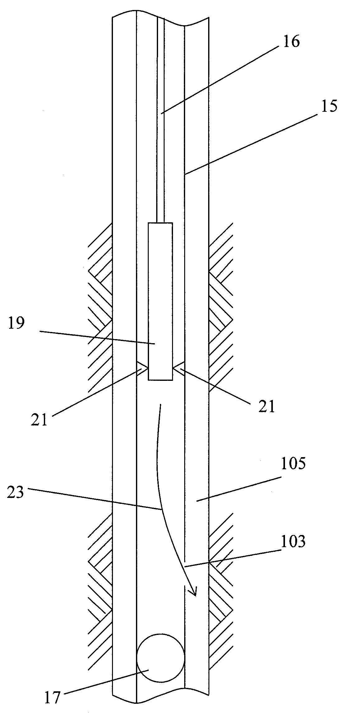
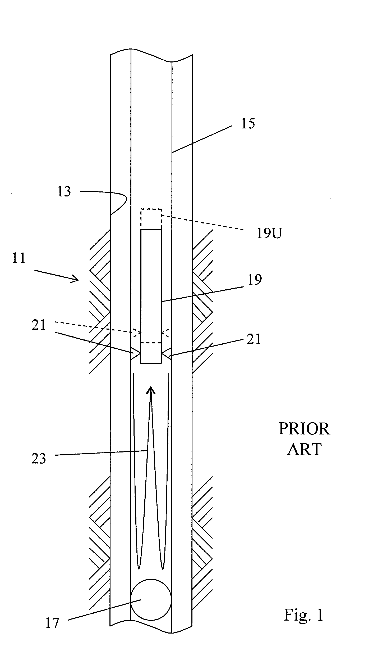
[0030]FIG. 1 illustrates the problem with the prior art technique of cutting pipe with closures. There is shown a borehole or well 11, which is typically lined with casing 13. Tubing 15 is run into the borehole 11. The tubing 15 has a closure 17 located therein. The closure 17 can be a check valve, a flapper valve, a plug, a collapsed plug, etc.

[0031]The tubing 15 is to be cut. A cutting torch 19 is lowered into the tubing 15 to a location above the closure 17. (The pipe on which the cutting torch 19 is suspended is not shown for illustrative purposes.) When the torch 19 is initiated, hot combustion fluids 21 are directed radially out from the torch. These combustion fluids create a pressure wave 23 that propagates down the pipe 15. Another pressure wave propagates up the pipe 15 to the surf...


PUM


Abstract

In cutting a downhole pipe in proximity to a closure in the pipe, the pipe is first perforated. A perforating torch is positioned with a pipe in proximity to the closure. The perforating torch produces cutting fluids in a first radial direction and produces an opening in the pipe, which cutting fluids produce a reaction force opposite to the first radial direction. This reaction force drives the perforating torch into contact with the pipe, anchoring it against any pressure wave produced by the cutting fluids and reflected off of the closure. Once the pipe is opened, a cutting torch is operated to sever the pipe. Any pressure wave generated by the cutting torch is vented through the opening.

Description

[0001]This application claims priority to provisional application Ser. No. 60 / 941,014, filed May 31, 2007.FIELD OF THE INVENTION [0002]The present invention relates to apparatuses and methods for cutting pipe in a borehole.BACKGROUND OF THE INVENTION [0003]In oil and gas wells, boreholes are drilled into the earth. Various types of pipe are lowered into the borehole. For example, casing provides a lining that is along the walls of the borehole. A drill string is a length of pipe used to drill the borehole. Coiled tubing is also used to drill. After drilling, tubing is located within the casing; oil and sometimes gas is produced to the surface through the tubing. In addition, wells are subjected to workover operations for maintenance.[0004]Occasionally, it becomes necessary to cut the pipe at a location inside of the borehole. For example, if coiled tubing is being used to drill, the end of the tubing may become stuck and cannot be removed from the borehole. As another example, in a ...

Claims


Application Information

Patent Timeline
IPC IPC(8): E21B43/11
CPCE21B29/02E21B29/06E21B43/11
Inventor ROBERTSON, MICHAEL C.
Owner ROBERTSON MICHAEL C
Learn More