
Amplifier

a technology of amplifiers and amplifiers, applied in the field of amplifiers, can solve the problems of inability to detect clipping, inability to feel sound volume, and inability to provide sound volume, so as to prevent unreasonably excessive input, provide feedback system stability, and attack time

Active Publication Date: 2008-12-04
YAMAHA CORP
View PDF3 Cites 7 Cited by
  • Summary
  • Abstract
  • Description
  • Claims
  • Application Information

AI Technical Summary

Benefits of technology

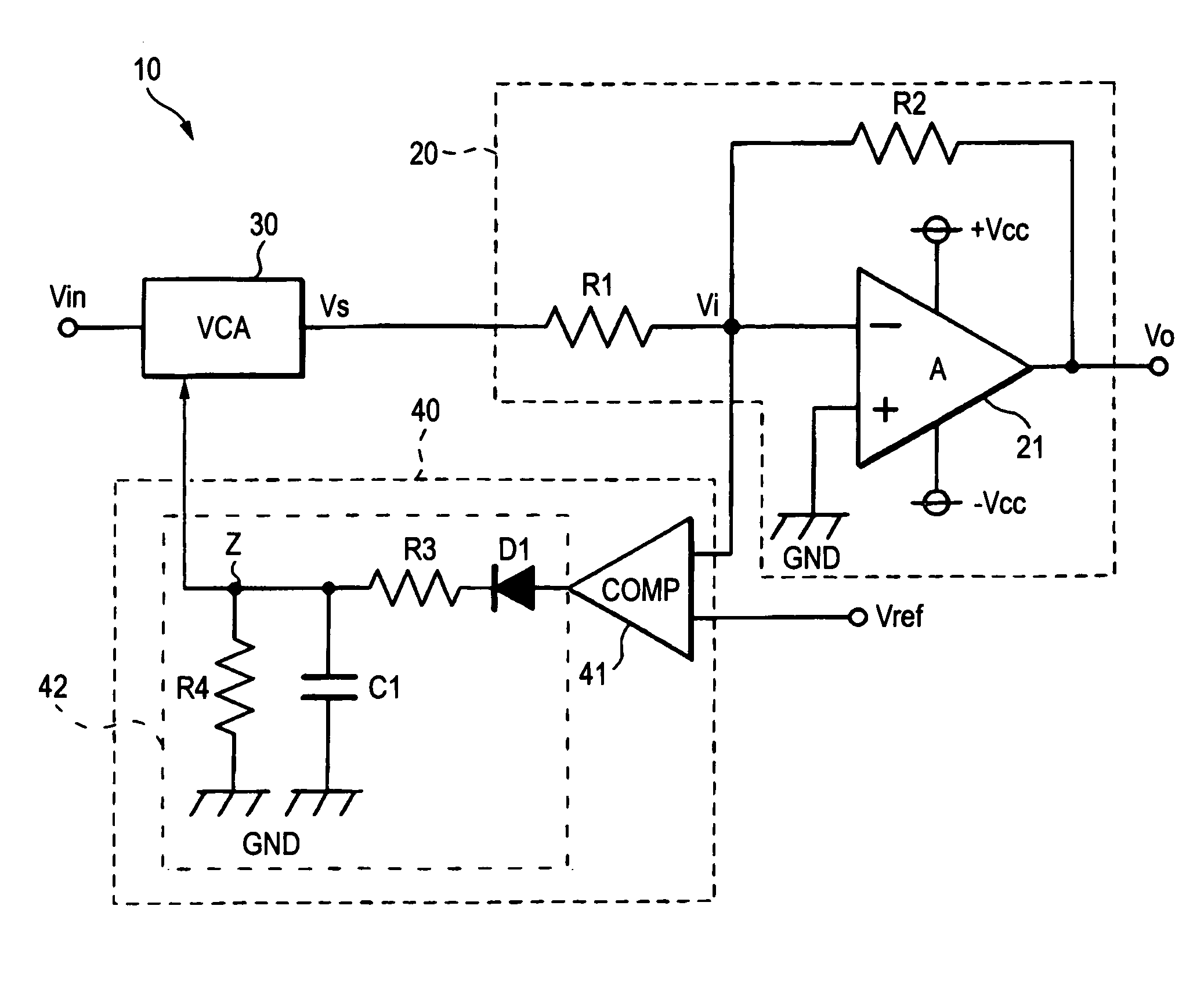
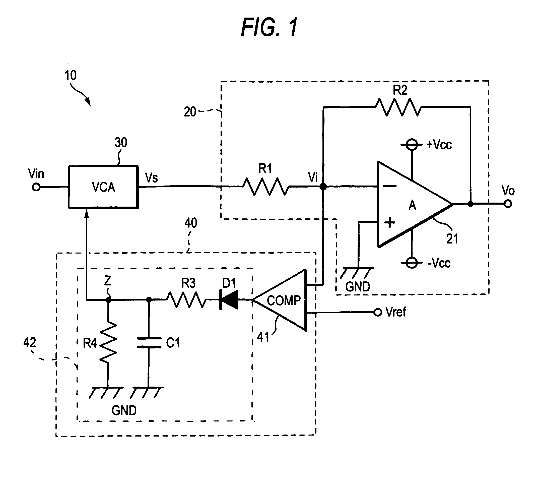
The invention is an amplifier that can control clipping by measuring the degree of excessive input. It includes a variable gain unit, a negative feedback amplifying unit, and a controller that compares the potential difference between the positive and negative phase input terminals of an operational amplifier with a reference potential to detect clipping. The controller adjusts the variable gain unit to control the clipping. This allows for quantitative control of clipping and prevents unreasonable excessive input without affecting the sound volume. The integrating means can use different time constants for the rising and trailing edges of the output signal of the comparison means to achieve a fast attack time and a slow release time to recover to an acceptable level.

Problems solved by technology

According to the technique described in JP-A-10-163769, since detection of an output potential alone does not allow reliable determination on the presence of clipping, an input signal is attenuated after occurrence of clipping is surely detected.
This control triggers attenuation too early and somewhat lacks the feeling of sound volume.

Method used


Image

  • Amplifier
  • Amplifier
  • Amplifier

Examples


Embodiment Construction

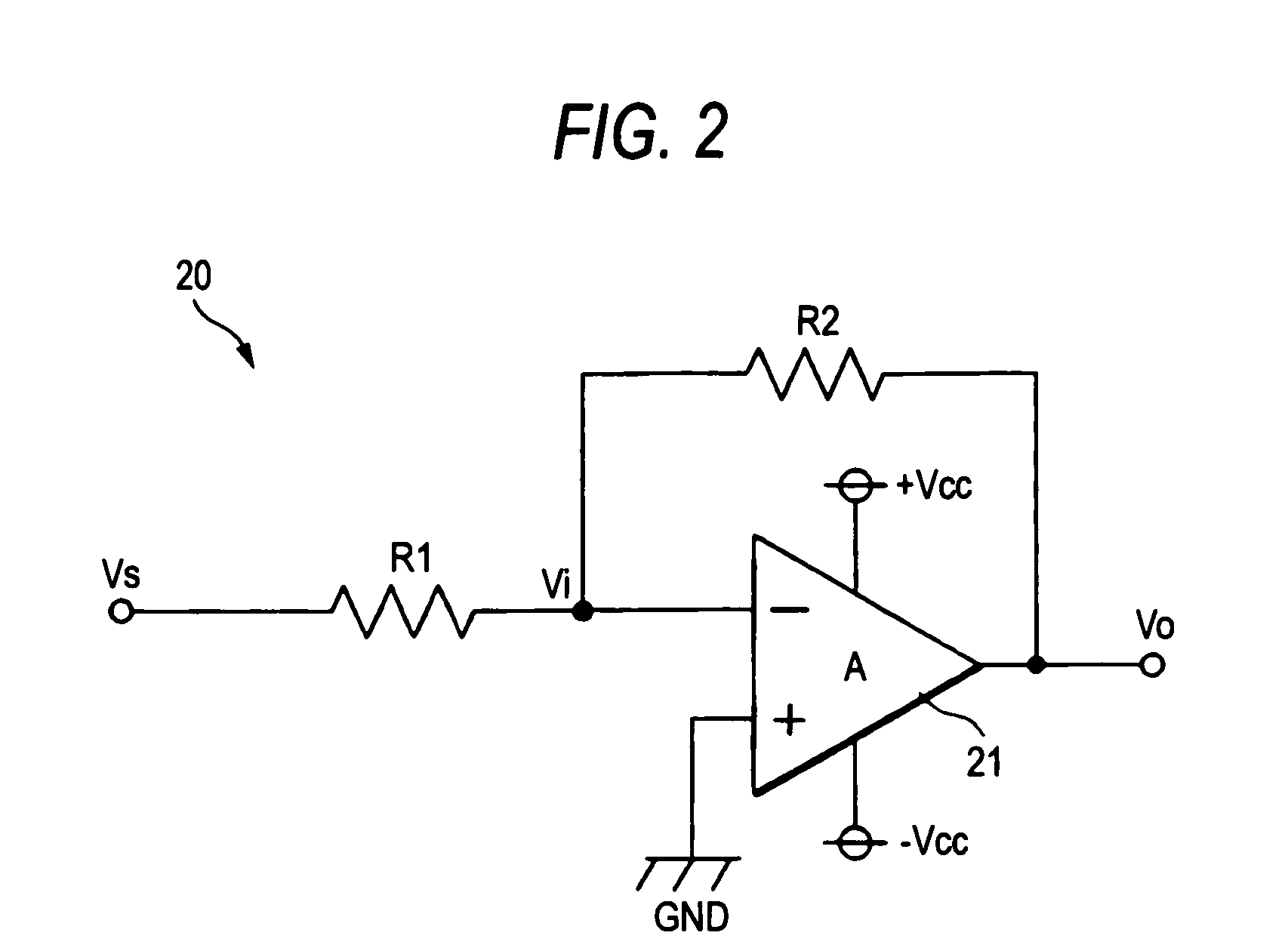
[0024]Embodiments of the invention will be described referring to drawings. FIG. 1 is a circuit diagram showing the configuration of an amplifier according to the embodiment. As shown in FIG. 1, an amplifier 10 for amplifying an input signal Vin and outputting the amplified signal as an output signal Vo includes: an inverting negative feedback amplifier circuit 20 having an operational amplifier 21 operating on the power potential of Vcc, a resistor R1 and a resistor R2; a voltage controlled attenuator (VCA) 30 for attenuating the input signal Vin as required; and a control circuit 40 for controlling the VCA 30.

[0025]The output of the VCA 30 is inputted as Vs to the negative feedback amplifier circuit 20. The control circuit 40 includes a comparator 41 for comparing the potential Vi of the inverting-input terminal of the operational amplifier 21 with the reference potential Vref of the operational amplifier 21, and a low-pass filter 42. The low-pass filter 42 functions as an integra...


PUM


Abstract

The amplifier comprises an inverting negative feedback amplifier circuit using an operational amplifier, a comparator for comparing the potential of the negative phase input terminal of the operational amplifier with the reference potential Vref of the comparator, and a low-pass filter. The imaginary short state of the operational amplifier is lost when clipping occurs on the output signal. It is thus possible to detect clipping by monitoring the potential of the negative phase input terminal.

Description

BACKGROUND OF THE INVENTION[0001]The present invention relates to an amplifier and in particular to an amplifier for detecting an excessive input at a predetermined level and controlling the attenuation of an input signal.[0002]An amplifier in the related art is designed to prevent clipping caused by an excessive input by attenuating an input signal on detecting that the output potential exceeds a predetermined value, for example, power potential. According to the technique described in JP-A-10-163769, since detection of an output potential alone does not allow reliable determination on the presence of clipping, an input signal is attenuated after occurrence of clipping is surely detected.[0003]The above technique is focused on prevention of clipping. Thus, when clipping occurs or there is a high probability that clipping will occur, the input signal is immediately attenuated. This control triggers attenuation too early and somewhat lacks the feeling of sound volume. Thus, attenuati...

Claims


Application Information

Patent Timeline
Patent Type & Authority Applications(United States)
IPC IPC(8): H03G3/00
CPCH03G3/3005H03G7/08H03F3/45H03G3/30
Inventor IWAMATSU, MASAYUKI
Owner YAMAHA CORP
Learn More