Suction nozzle for vacuum cleaner

Active Publication Date: 2008-12-11
SAMSUNG GWANGJU ELECTRONICS CO LTD
View PDF4 Cites 18 Cited by
  • Summary
  • Abstract
  • Description
  • Claims
  • Application Information

AI Technical Summary

Benefits of technology

[0009]The exemplary embodiments of the present disclosure have been developed in order to overcome the above drawbacks and other problems associated with conventionally-arranged vacuum cleaners. An aspect of the present

Problems solved by technology

However, when cleaning the surface to be cleaned such as a carpet using only the suction force, long thin contaminants such as human hair, or pet fur (hereinafter individually and collectively referred to as “fur”) can

Method used


Image

  • Suction nozzle for vacuum cleaner
  • Suction nozzle for vacuum cleaner
  • Suction nozzle for vacuum cleaner

Examples


Example

[0034]Throughout the drawings, like reference numerals will be understood to refer to like parts, components and structures.

DETAILED DESCRIPTION OF THE EXEMPLARY EMBODIMENTS

[0035]Hereinafter, certain exemplary embodiments of the present disclosure will be described in detail with reference to the accompanying drawings.

[0036]The matters defined in the description, such as a detailed construction and elements thereof, are provided to assist in a comprehensive understanding of the invention. Thus, it is apparent that the present disclosure may be carried out without those defined matters. Also, well-known functions or constructions are omitted to provide a clear and concise description of exemplary embodiments of the present disclosure.

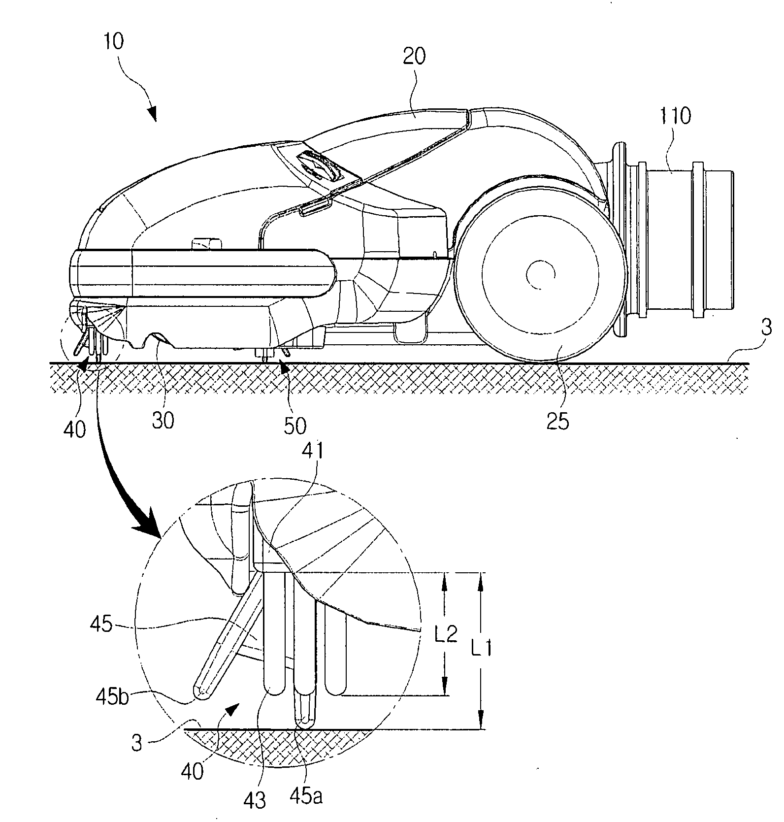
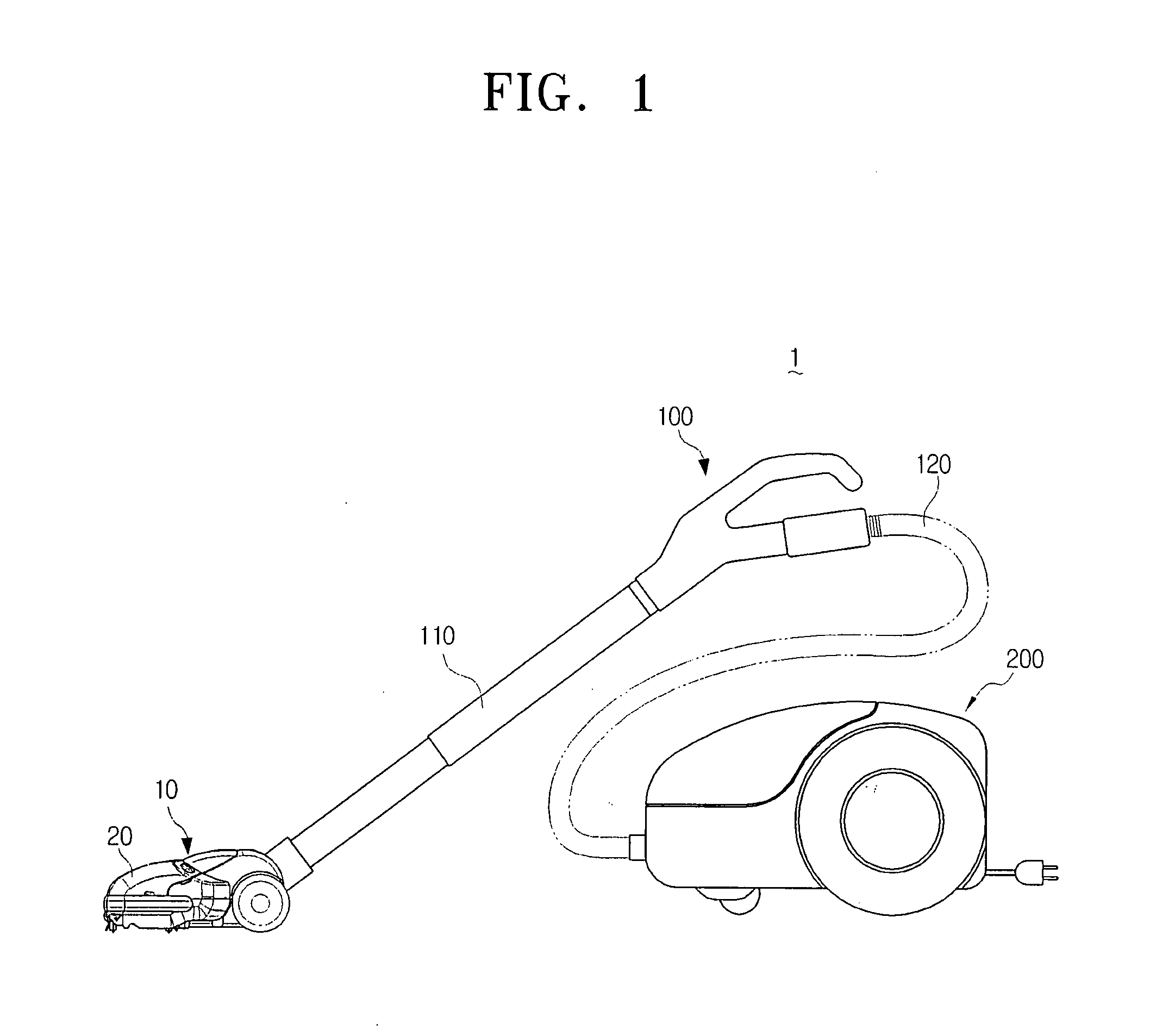
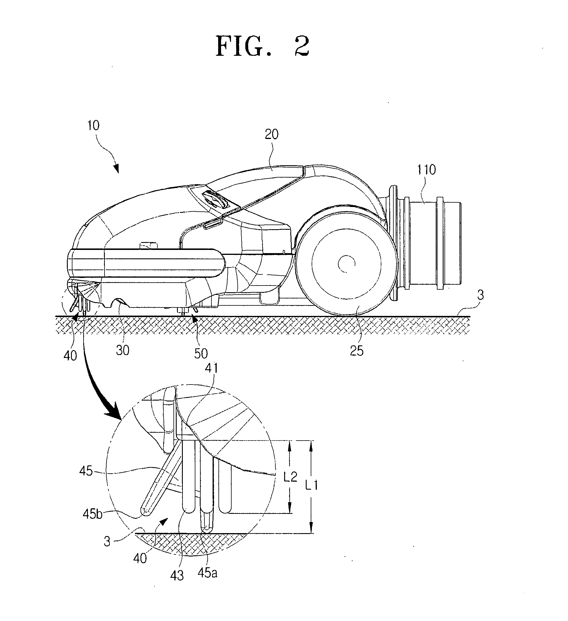
[0037]FIG. 1 is a side view illustrating a vacuum cleaner 1 having a suction nozzle 10 according to an exemplary embodiment of the present disclosure, and FIG. 2 is a side view illustrating the suction nozzle 10 of the vacuum cleaner 1 of FIG. 1. FIGS. 3...


PUM


Abstract

The present disclosure relates to a suction nozzle for a vacuum cleaner, which includes a nozzle body having a contaminants suction port formed on a bottom surface thereof, and a fur-removing member having a fur-removing body rotatably disposed at a side of the contaminants suction port on the nozzle body, a fur-removing portion formed in a plurality of pins vertically to the fur-removing body, and a plurality of rotation cams, wherein when the nozzle body moves in a first direction, the plurality of rotation cams forces the fur-removing body to rotate so that a leading end of the fur-removing portion is spaced apart from a surface to be cleaned.

Description

CROSS-REFERENCE TO RELATED APPLICATIONS[0001]This application claims the benefit under 35 U.S.C. §119(a) from Korean Patent Application No. 2007-56720 filed Jun. 11, 2007 in the Korean Intellectual Property Office, the disclosure of which is incorporated herein by reference in its entirety.BACKGROUND OF THE INVENTION[0002]1. Field of the Invention[0003]The present disclosure relates to a vacuum cleaner. More particularly, the present disclosure relates to a suction nozzle for a vacuum cleaner having a fur removing member.[0004]2. Description of the Related Art[0005]Generally, a conventionally-arranged vacuum cleaner has a suction nozzle to draw in contaminants with air from a surface to be cleaned.[0006]The suction nozzle is structured to move on the surface to be cleaned, and has, on a bottom surface thereof, a contaminants suction port to draw in contaminants from the surface to be cleaned. When a vacuum generator in a vacuum cleaner body operates to generate a suction force, cont...

Claims


Application Information

Patent Timeline
IPC IPC(8): A47L9/04A47L9/00A47L9/02
CPCA47L9/0666A47L9/06A47L9/02A47L9/04
Inventor OH, JANG-KEUN
Owner SAMSUNG GWANGJU ELECTRONICS CO LTD
Why Eureka
Try Eureka