Lock with a swing bolt and an actuator assembly thereof

a technology of swing bolts and actuators, applied in the field of swing bolts, can solve the problems of large power consumption, difficult to add other functional elements to the lock body, and damage to both the operating element and the solenoid, so as to improve the safety performance of the lock, reduce the surface dimensions of the bolt, and reduce the stress concentration

Inactive Publication Date: 2008-12-11
SHANGHAI BUDDY TECHONOLOGICAL
View PDF9 Cites 61 Cited by
  • Summary
  • Abstract
  • Description
  • Claims
  • Application Information

AI Technical Summary

Benefits of technology

[0009]The object of the present invention is to provide a lock with a swing bolt which is capable of protecting an actuator assembly from being damaged by an illegal and violent unlocking action and capable of dividing an illegal and violent force into components to act on several portions, and to provide an actuator assembly which is easy to reach an engagement between a male threaded member and a female threaded member and to protect a motor from being forcibly stopped.

Problems solved by technology

A linear contact between the bolt and the head of the operating element will bring about a stress concentration, and this trends to cause some damage of both the operating element and the solenoid.
Because both of them occupy a larger space in the lock body, the volume available in the lock body becomes smaller and so it is very difficult to add other functional elements in the lock body.
Moreover, in the lock of the prior art for controlling a safe door, there exist the following problems with their actuator assembly.
If a one-directional solenoid is used (returned by a spring), such a solenoid causes a larger power consumption, this is especially disadvantageous for a safe's lock which uses a dry battery for power supply; if a bi-directional solenoid is used, apart from complication, it requires a even larger mounting space.
As such, in the case of rotating at a high speed, it is very difficult for the screw to engage with the nut exactly, which trends to cause a jam between the screw and the nut so as to further bring about damages of the screw-and-nut mechanism or the motor.

Method used


Image

  • Lock with a swing bolt and an actuator assembly thereof
  • Lock with a swing bolt and an actuator assembly thereof
  • Lock with a swing bolt and an actuator assembly thereof

Examples


Embodiment Construction

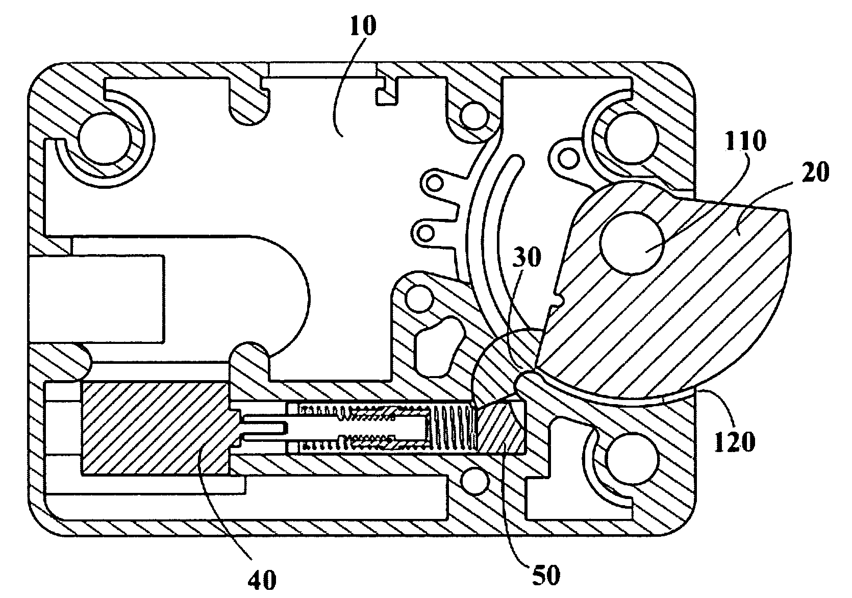
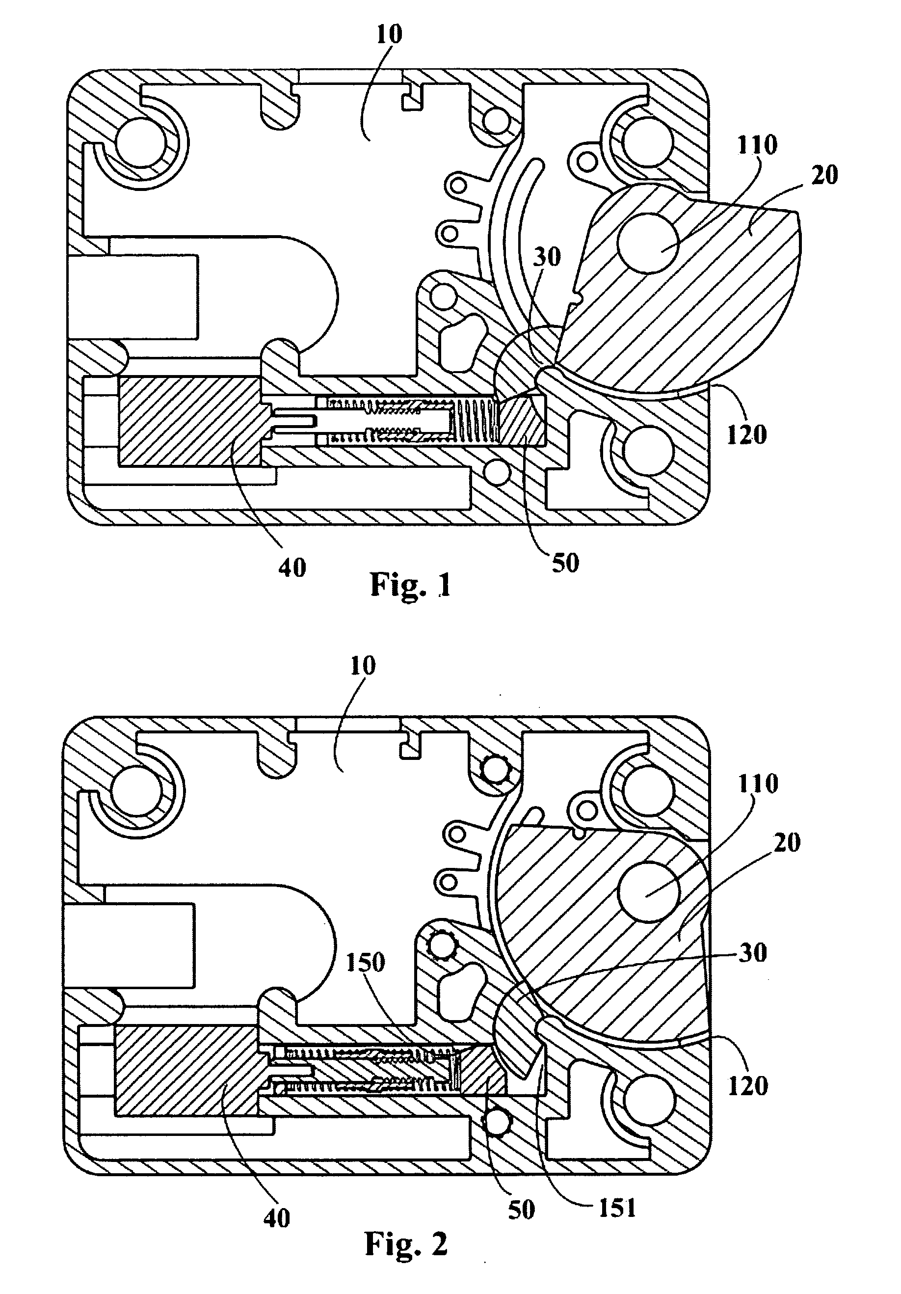
[0045]As shown in FIG. 1 and FIG. 2, a sectorial bolt 20 is mounted, with a through hole 24 thereof, on a shaft 110 in a housing 10, and it can pivot about the shaft in a range of about 90 degree. The height of a stub 31 of a block member 30 and the height of a first sliding chute are substantially equal to the plate thickness of the bolt 20, and hence they move in the same plane.

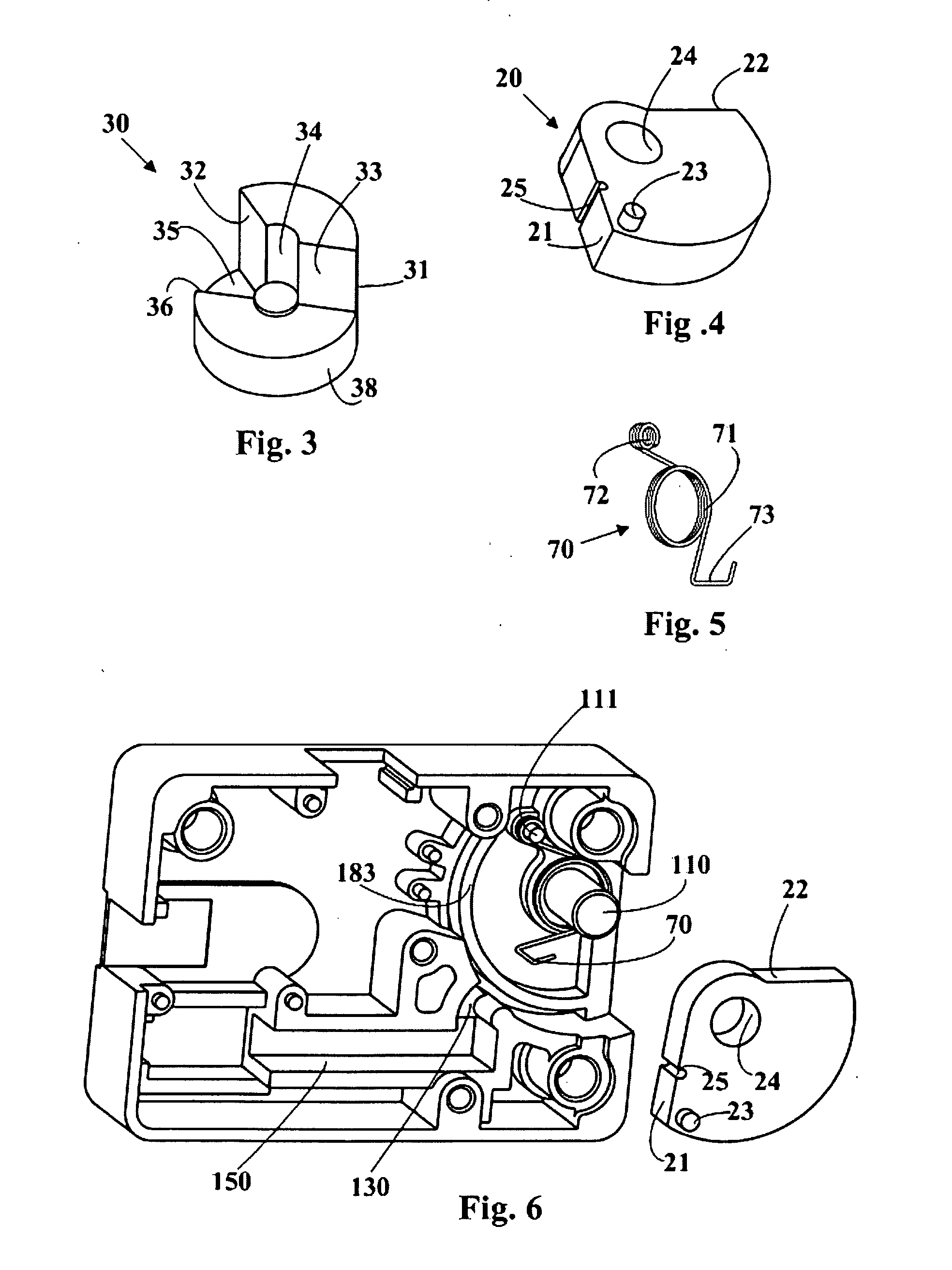
[0046]Referring to FIG. 3 and FIG. 4, during assembling, the bolt 20 is first put in and then the stub 31 of the block member 30 is put in a first sliding chute 130 in the housing 10. The first sliding chute 130 is formed by a convex semi-cylindrical surface 131 provided in the housing 10 and an opposite concave partially-cylindrical surface 132, the distance between the two surfaces is just equal to the radial thickness of the sectorial portion of the stub 31 of the block member 30, however, with a suitable clearance for a slidable fit between them. After the block member 30 is assembled in position, the c...


PUM


Abstract

A lock with a swing bolt, comprises: a housing having an opening for a bolt; a cover which is complementary to the housing; a bolt movable between a locked position and an un-locked position through the opening; a controllable locking means to prevent the movement of the bolt to the un-locked position; wherein the locking means including: a block member, which is placed in a first sliding chute formed in the housing with a slidable fit between the block member and the first sliding chute; an actuator assembly having a follower which is placed in a second sliding chute formed in the housings with a slidable fit between the follower and the second sliding chute; one end of the block member being engaged with the bolt in a surface contact, the other end of the block member is engaged with the follower in a surface contact.

Description

FIELD OF THE INVENTION[0001]This invention relates to a lock, particularly to a lock with swing bolt.BACKGROUND ART[0002]In the prior art, in a lock for controlling a door of a safe, the body of the lock generally employs a straight-in / straight-out and square-shaped bolt or a wedge-shaped bolt. In a normal condition (locked-up condition), the bolt is restricted to be un-retracted, and it imposes a clog against a doorknob or door-release. In order to release the bolt from being restricted, a correct code should be input into the code entry device of the safe and be confirmed by a preset program in the device, and then an actuator assembly will act on to allow the lock to be unlocked. The bolt is reset to its normal condition (locked-up condition) by means of a return spring.[0003]U.S. Pat. No. 5,142,890, U.S. Pat. No. 5,134,870 and U.S. Pat. No. 6,786,519 disclose several technical solutions of locks with swing bolts. In those solutions, a bolt is D-shaped (i.e., semicircular or a 18...

Claims


Application Information

Patent Timeline
Patent Type & Authority Applications(United States)
IPC IPC(8): E05C3/12E05B47/06
CPCE05B47/0012E05B65/0075E05B2015/0448E05B2047/0093E05B2047/0023E05B2047/0031E05B2047/0016E05B47/06E05B47/0607Y10T292/1075Y10T292/1082Y10T70/7062Y10T292/1077
Inventor YUAN, MENGXIAO
Owner SHANGHAI BUDDY TECHONOLOGICAL
Why Eureka
Try Eureka