Spray actuator

a technology of actuator and spray rod, which is applied in the direction of liquid handling, applications, instruments, etc., can solve the problems of difficult assembly and achieve the effect of simple basic movements and easy identification

Active Publication Date: 2010-07-20
SUMMIT PACKAGING SYST INC
View PDF44 Cites 53 Cited by
  • Summary
  • Abstract
  • Description
  • Claims
  • Application Information

AI Technical Summary

Benefits of technology

[0010]It is another object of the present invention to provide an aerosol spray actuator wherein the actuator can be positioned in an operative or inoperative position analogous to an on and off position where in the inoperative position the actuator is prevented from actuating a valve of the container.
[0011]It is another object of the present invention to provide an aerosol spray actuator wherein the operative or inoperative position is easily attained by simple basic movements by the user.
[0012]It is still another object of the present invention to provide an aerosol spray actuator wherein the operative and inoperative position of the cap is visually, tactile or audibly easily identified by any user.

Problems solved by technology

Because of their functionality, locking spray actuators are usually composed of numerous parts which are firstly very difficult to mold, and secondly and perhaps more importantly, difficult to assemble.

Method used


Image

  • Spray actuator
  • Spray actuator
  • Spray actuator

Examples


Embodiment Construction

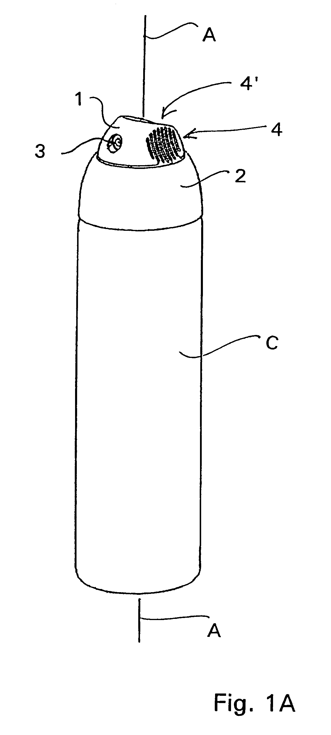
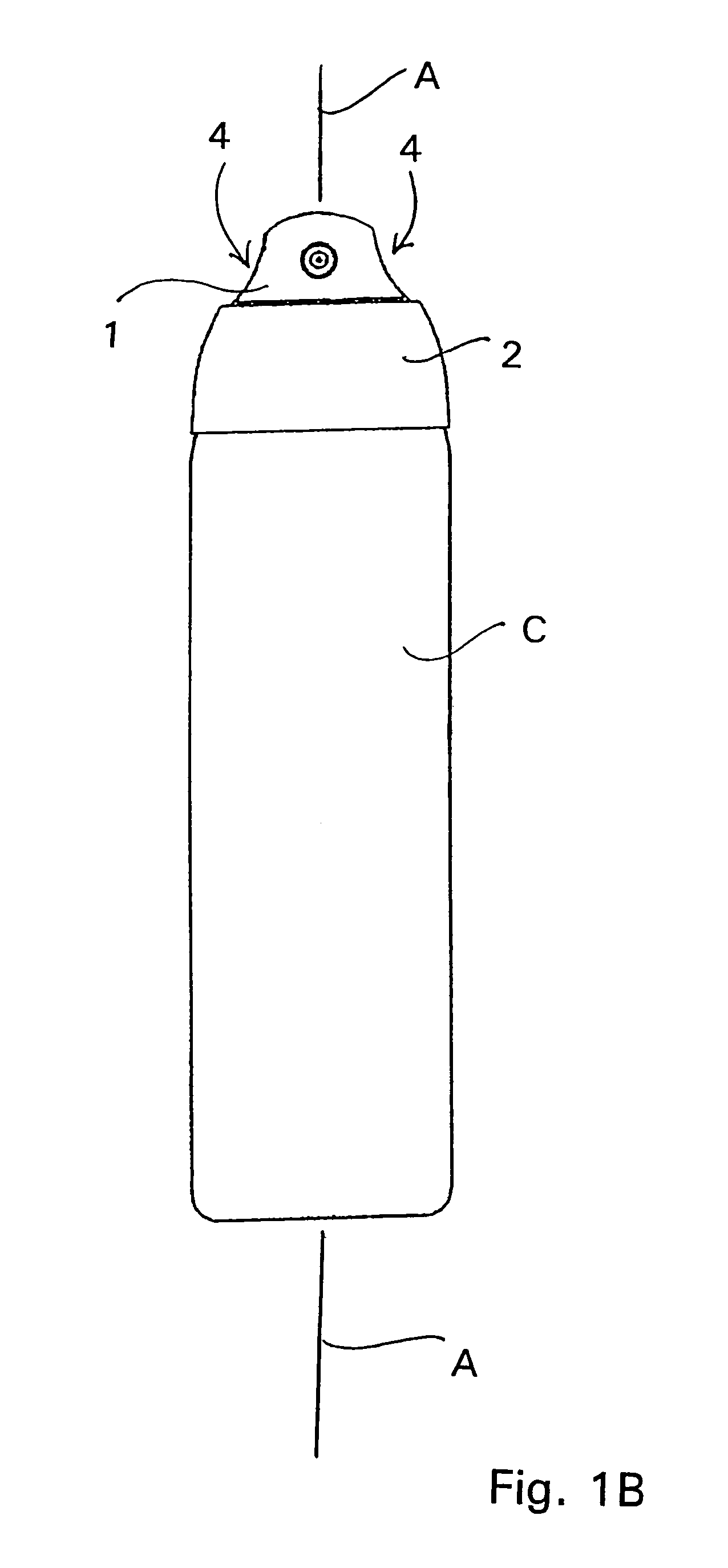
[0039]A twist top actuator, shown in FIGS. 1A-B, may be provided with three (3) main parts generally supported on an aerosol spray can C, an actuating button 1, a base or skirt 2 and a nozzle 3. The actuating button 1 in the present embodiment is radially rotatable about a longitudinal axis A relative to the base 2 so that there is defined an actuating position and a non-actuating position of the button 1 relative to the base 2. By “radially rotatable” it is to be understood that the button 1 has a circumference defined by a radius extending from and rotatable about the longitudinal axis A. The button 1 is provided on either side with indented or concave finger gripable sections 4 which allow a user to radially rotate the button 1 relative to the base 2. Another slightly indented, angled or concave section may be provided in a top most portion of the button 1 to provide a user with an appropriate and ergonomic finger pad 4′ to depress the button relative to the base 2.

[0040]When the...


PUM


Abstract

An aerosol spray actuator for a pressurized aerosol canister and in particular trigger or button actuated spray actuators having three main parts to simplify the mechanical moving parts of a spray actuator. An actuator button, an actuator base and finally a nozzle piece being inserted at the very end of a product dispensing passage embodied either in the body or the trigger part. A mechanism for permitting and blocking the actuation of the spray actuator is also provided so that inadvertent operation of the actuator can be prevented.

Description

FIELD OF THE INVENTION[0001]This invention relates to an aerosol spray actuator for dispensing an aerosolized product from a container, and more specifically, to certain new and useful improvements in the configuration, function, manufacturing and structure of an aerosol spray actuator having an actuating position for dispensing aerosol from a container and an unactuated position where the spray actuator is prevented from actuating a valve in the container.BACKGROUND OF THE INVENTION[0002]Aerosol containers containing a wide variety of active components or contents under pressure such as insect repellents, insecticides, hairsprays, creams or foams and so on have been marketed widely for household, commercial and industrial purposes.[0003]In conventional aerosol containers, the outlet is normally a tubular valve stem element springably biased into a closed position which, when depressed into the body of the container opens the valve and releases the contents which are held under pres...

Claims


Application Information

Patent Timeline
Patent Type & Authority Patents(United States)
IPC IPC(8): B65D83/00
CPCB65D83/22B65D83/206
Inventor STRAND, TORALF H.LACEY, THOMAS G.
Owner SUMMIT PACKAGING SYST INC
Why Eureka
Try Eureka