Indexable end-milling insert

a technology of endmilling insert and indexing, which is applied in the direction of shaping cutters, manufacturing tools, transportation and packaging, etc., can solve the problems of insufficient two solutions in certain respects, difficult to master one of them, and only two usable cutting edges in the cutting insert, etc., to achieve good chip formation, long service life of the cutting insert, wear evenly and slowly

Active Publication Date: 2008-12-11
SANDVIK INTELLECTUAL PROPERTY AB
View PDF14 Cites 88 Cited by
  • Summary
  • Abstract
  • Description
  • Claims
  • Application Information

AI Technical Summary

Benefits of technology

[0011]a) has four easy-cutting and strong main edges, which provide good chip formation and flexible chi...

Problems solved by technology

However, the last-mentioned advantage has been gained at the price of the disadvantage that the cutting insert includes only two usable cutting edges.
However, the task of designing four-edged end-milling inserts involves a number of awkward weighings and problems because of the complicated space geometry of the milling-cutter tools and cutting inserts, the most difficult one to master of which is the design of the different clearances of the cutting insert.
Notwithstanding the fac...

Method used


Image

  • Indexable end-milling insert
  • Indexable end-milling insert
  • Indexable end-milling insert

Examples


Embodiment Construction

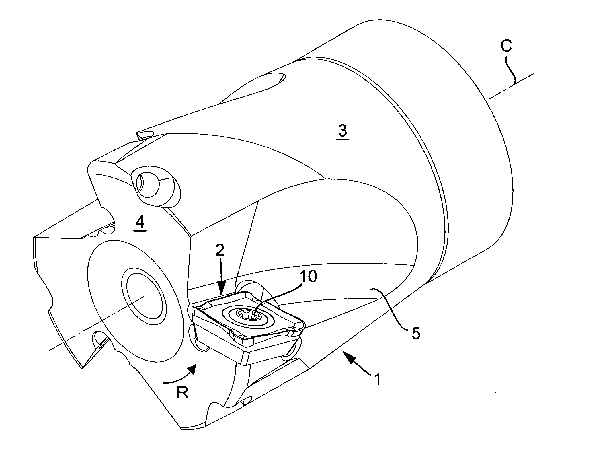
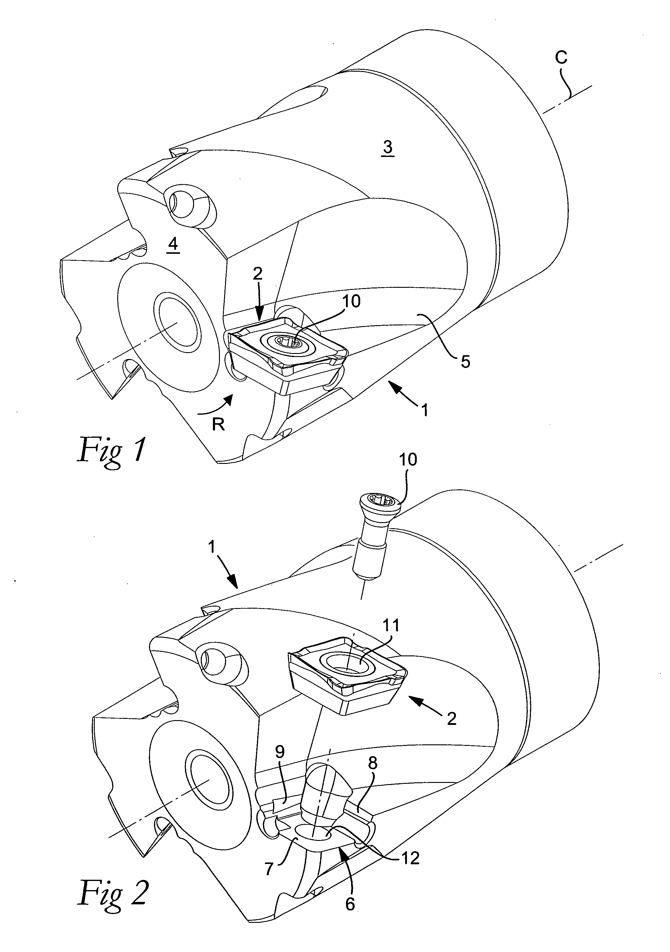
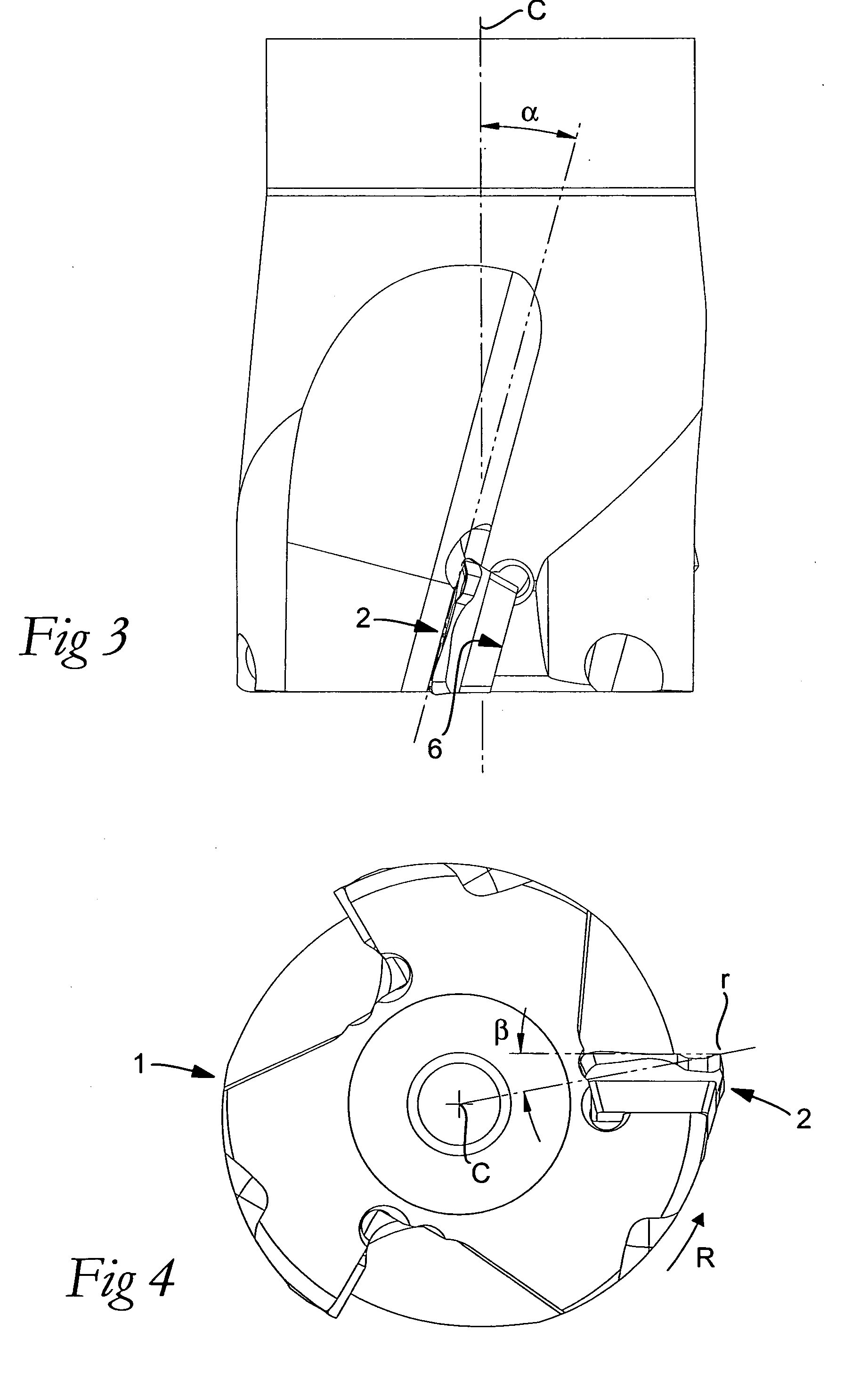
[0033]Below, a preferred embodiment of the cutting insert according to an embodiment of the invention will be described in detail, reference being made to the different drawing figures. First, a milling or basic body co-operating with the cutting insert will be described in more detail, and then the cutting insert as such.

[0034]The assembled milling-cutter tool shown in FIGS. 1-4 includes a basic body 1 and a plurality of cutting inserts 2, only one of which is shown in the respective figure. The basic body or the milling cutter body 1 is rotatable in the direction of rotation R around a center axis designated C, and has as a rotationally symmetrical envelope surface 3, as well as a front end surface 4. In the envelope surface as well as the end surface, a number of chip pockets 5 open, each one of which includes an insert seat 6 for the receipt of a cutting insert 2. In the example, the number of chip pockets and cutting inserts, respectively, is three.

[0035]In this case, the inser...


PUM

PropertyMeasurementUnit
Angleaaaaaaaaaa
Angleaaaaaaaaaa
Distanceaaaaaaaaaa

Abstract

An indexable end-milling insert including an underside, an upperside and a plurality of cutting edges that are formed between the upperside and a number of clearance sides and that include a chip-removing main edge as well as a surface-wiping wiper edge. The cutting insert has a square basic shape and includes four main edges and four wiper edges that are countersunk to a lower level than the main edges. The wiper edge is included in a lip projecting in relation to a secondary clearance surface and has a tertiary clearance surface, which laterally transforms into a primary clearance surface. The primary clearance surface has a width that decreases from the two opposite ends thereof toward a section having a smallest width therebetween.

Description

[0001]This application claims priority under 35 U.S.C. § 119 to Swedish Patent Application No. 0701370-9, filed on Jun. 5, 2007, which is incorporated by reference herein in its entirety.FIELD OF THE INVENTION[0002]The present invention relates generally to an indexable end-milling insert of the type that includes an underside, an upperside and a plurality of cutting edges that are formed between the upperside and a number of clearance sides, and individually include a chip-removing main edge as well as a surface-wiping wiper edge that transforms into the main edge via a corner of the cutting insert. The main edge extends arched between a first end and an opposite second end, which—in relation to the underside—is situated on a higher level than the first end. The main edge is delimited between a chip surface situated inside a cutting-edge line, and a convexly arched, primary clearance surface positioned outside the cutting-edge line and below which there is a secondary clearance sur...

Claims


Application Information

Patent Timeline
IPC IPC(8): B26D1/00B26D1/12
CPCB23C5/202B23C5/2213B23C2200/205Y10T407/191Y10T407/23Y10T407/235B23C2200/208B23C2200/243B23C5/20B23C5/02B23B27/16B23B51/00B23B51/0008B23B2205/12
Inventor ENGSTROM, TORDPANTZAR, GORANSVEDBERG, PATRIKASTROM, MAGNUS
Owner SANDVIK INTELLECTUAL PROPERTY AB
Why Eureka
Try Eureka