Reflective secondary optic for concentrated photovoltaic systems

a secondary optic and concentrated photovoltaic technology, applied in the safety of solar heat collectors, solar heat systems, lighting and heating apparatuses, etc., can solve the problems of increasing wind load, reducing the energy density per unit land area, and affecting the maintenance

Inactive Publication Date: 2008-12-18
GREENVOLTS INC
View PDF5 Cites 44 Cited by
  • Summary
  • Abstract
  • Description
  • Claims
  • Application Information

AI Technical Summary

Problems solved by technology

This reduces the energy density per unit land area achievable.
This requires larger scale materials, increases wind loading, and makes maintenance difficult and dangerous.
Finally, a high degree of tracking accuracy is difficult due to the small moment arm of the drive mechanism, usually mounted atop the pole.
Such transmissive secondary optics are heavy and expensive to manufacture.
For example, the grinding process is slow and molding requires an expensive tool to press it into shape.
Transmissive secondary optics are also subject to fracturing from handling or due to thermal shock.
In addition, there are transmission losses associated with transmissive secondary optics no matter which angle at which energy arrives at the collector.

Method used


Image

  • Reflective secondary optic for concentrated photovoltaic systems
  • Reflective secondary optic for concentrated photovoltaic systems
  • Reflective secondary optic for concentrated photovoltaic systems

Examples


Embodiment Construction

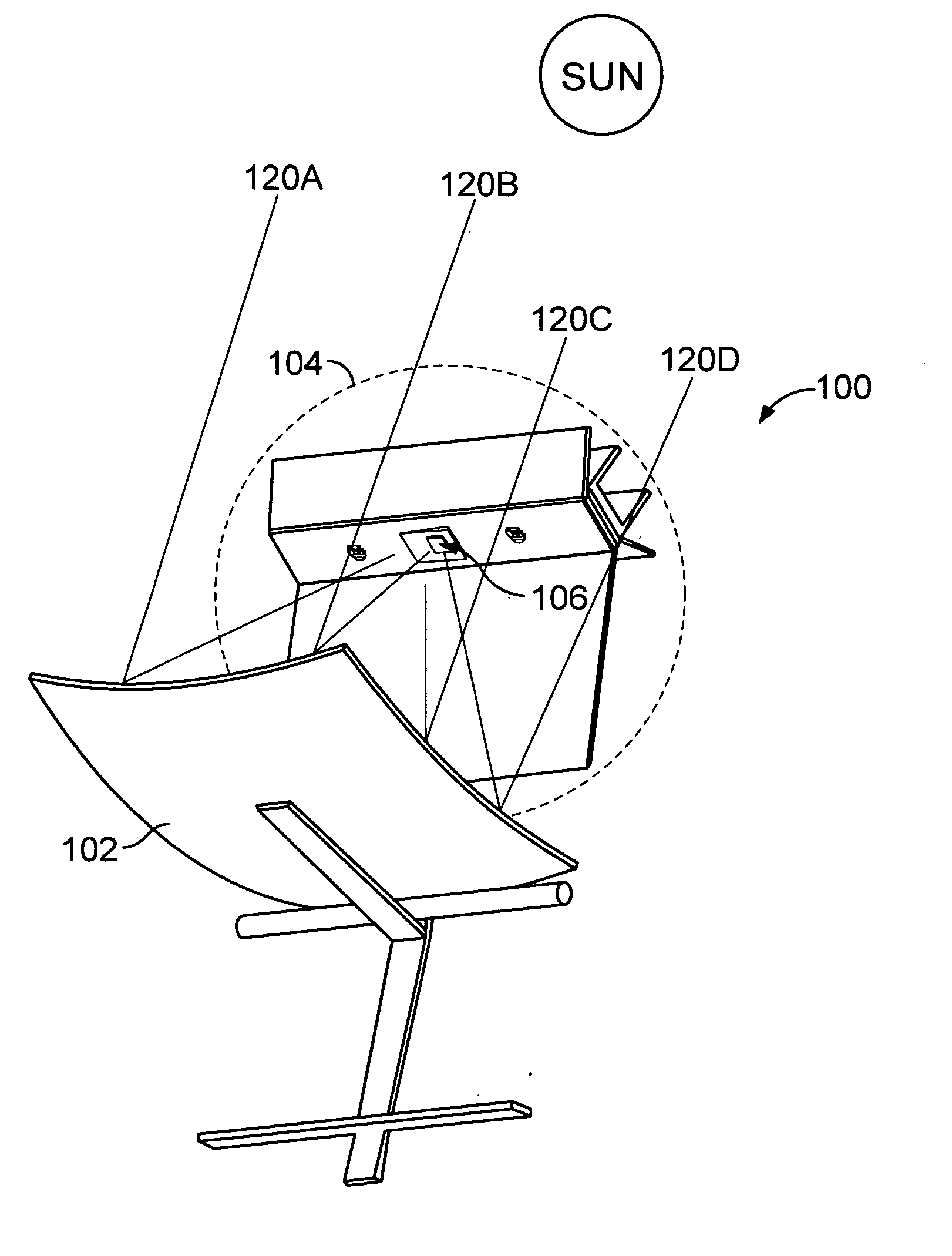
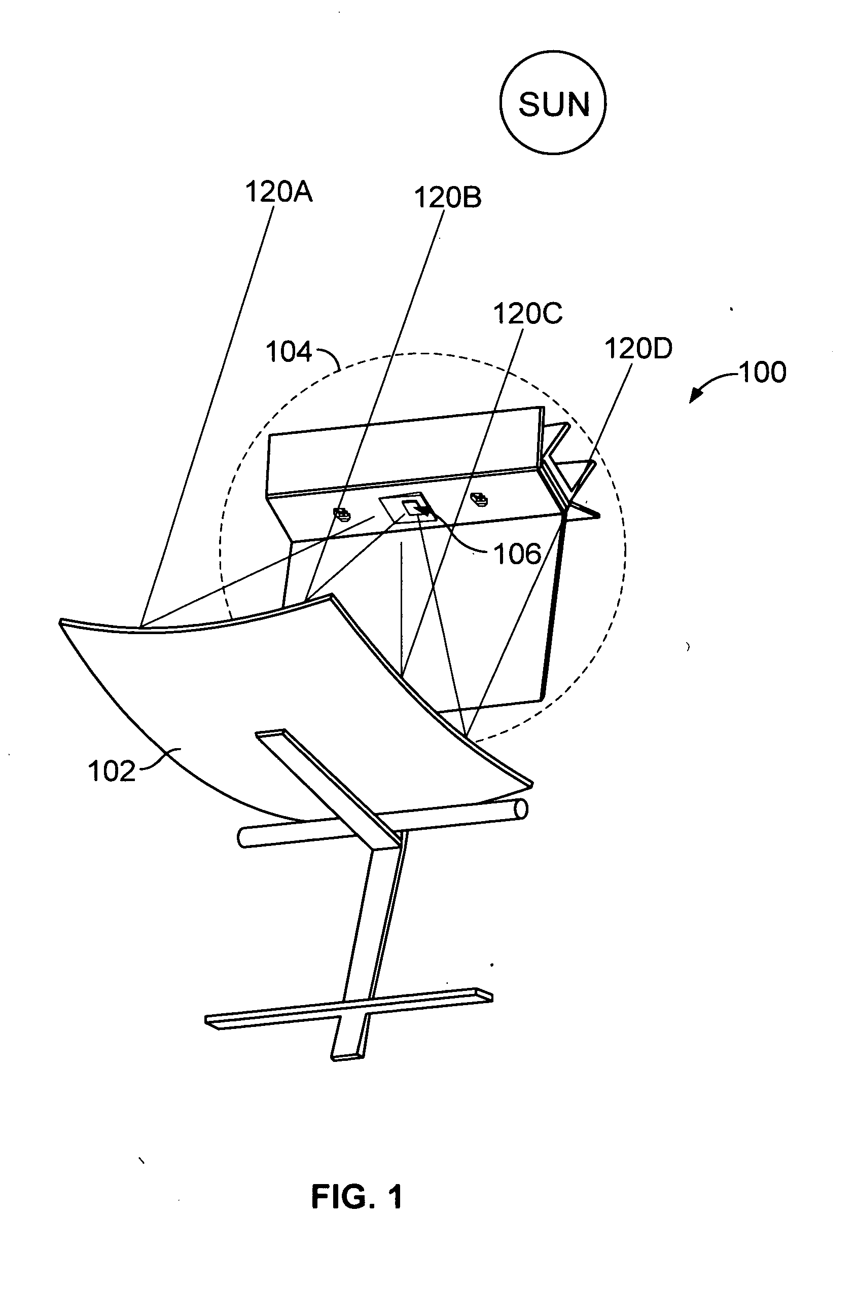
[0041]The invention can be implemented in numerous ways, including as a process, an apparatus, a system, or a composition of matter. In this specification, these implementations, or any other form that the invention may take, may be referred to as techniques. A component such as a solar cell described as being configured to perform a task includes both a general component that is temporarily configured to perform the task at a given time or a specific component that is manufactured to perform the task. In general, the order of the steps of disclosed processes may be altered within the scope of the invention. As used herein, the term ‘cell’ or ‘solar cell’ refers to one or more devices that converts sunlight to electricity, such as a photovoltaic cell.

[0042]A detailed description of one or more embodiments of the invention is provided below along with accompanying figures that illustrate the principles of the invention. The invention is described in connection with such embodiments, ...


PUM


Abstract

A solar power system is disclosed. The solar power system includes: a solar energy receiving solar collector; a reflective secondary optical element comprising one or more sheets, wherein the one or more sheets are arranged to form a hollow structure having an interior surface, an exterior surface, an entry aperture, and an exit aperture, such that at least a portion of the interior of the hollow structure is reflective and wherein the hollow structure is positioned to receive energy from the solar collector through the entry aperture, reflect the energy from the interior surface of the hollow structure, and output the reflected energy through the exit aperture; and a receiver positioned to receive the reflected energy from the exit aperture. The energy from the solar collector is reflected and thereby directed through the exit aperture to the receiver by the reflective secondary optical element.

Description

CROSS REFERENCE TO OTHER APPLICATIONS[0001]This application claims priority to U.S. Provisional Patent Application No. 60 / 933,341 (Attorney Docket No. GREEP007+) entitled REFLECTIVE SECONDARY OPTIC FOR CONCENTRATED PHOTOVOLTAIC SYSTEMS filed Jun. 6, 2007 which is incorporated herein by reference for all purposes.BACKGROUND OF THE INVENTION[0002]Solar power systems include concentrating and non-concentrating systems. In non-concentrating solar power systems, the solar cell receives direct and indirect sunlight. An example of a non-concentrating solar power system is a flat panel of photovoltaic (PV) cells that directly receive sunlight. In concentrating solar power systems, the solar cell receives indirect sunlight that has been concentrated by a collector and directed at the receiver. An example of a concentrating solar power system is a parabolic collector in which a solar cell is located at the focus.[0003]Solar power systems include tracking and non-tracking solar power systems. ...

Claims


Application Information

Patent Timeline
Patent Type & Authority Applications(United States)
IPC IPC(8): H01L31/00
CPCF24J2/07F24J2/10F24J2/14F24J2/18F24J2/32F24J2/461H01L31/0547F24J2002/5479Y02E10/41Y02E10/44Y02E10/45Y02E10/47Y02E10/52F24J2/542F24S10/95F24S20/20F24S23/00F24S23/70F24S23/74F24S23/79F24S30/452F24S40/20F24S50/20F24S2030/145Y02E10/40
Inventor CART, ROBERTFINE, KEVIN RICHARDSURENDRAN, SANDHEEP KUMAR
Owner GREENVOLTS INC
Why Eureka
Try Eureka