
Power-Controllable Outlet Receptacle

a power strip and outlet receptacle technology, applied in relays, air-break switches, coupling device connections, etc., can solve the problems of troublesome user switching on/off the switch of the respective outlet one by, unnecessary current consumption, and risk of overloading the power strip all the time, so as to prevent overload

Inactive Publication Date: 2008-12-18
LIM CO LTD
View PDF3 Cites 75 Cited by
  • Summary
  • Abstract
  • Description
  • Claims
  • Application Information

AI Technical Summary

Benefits of technology

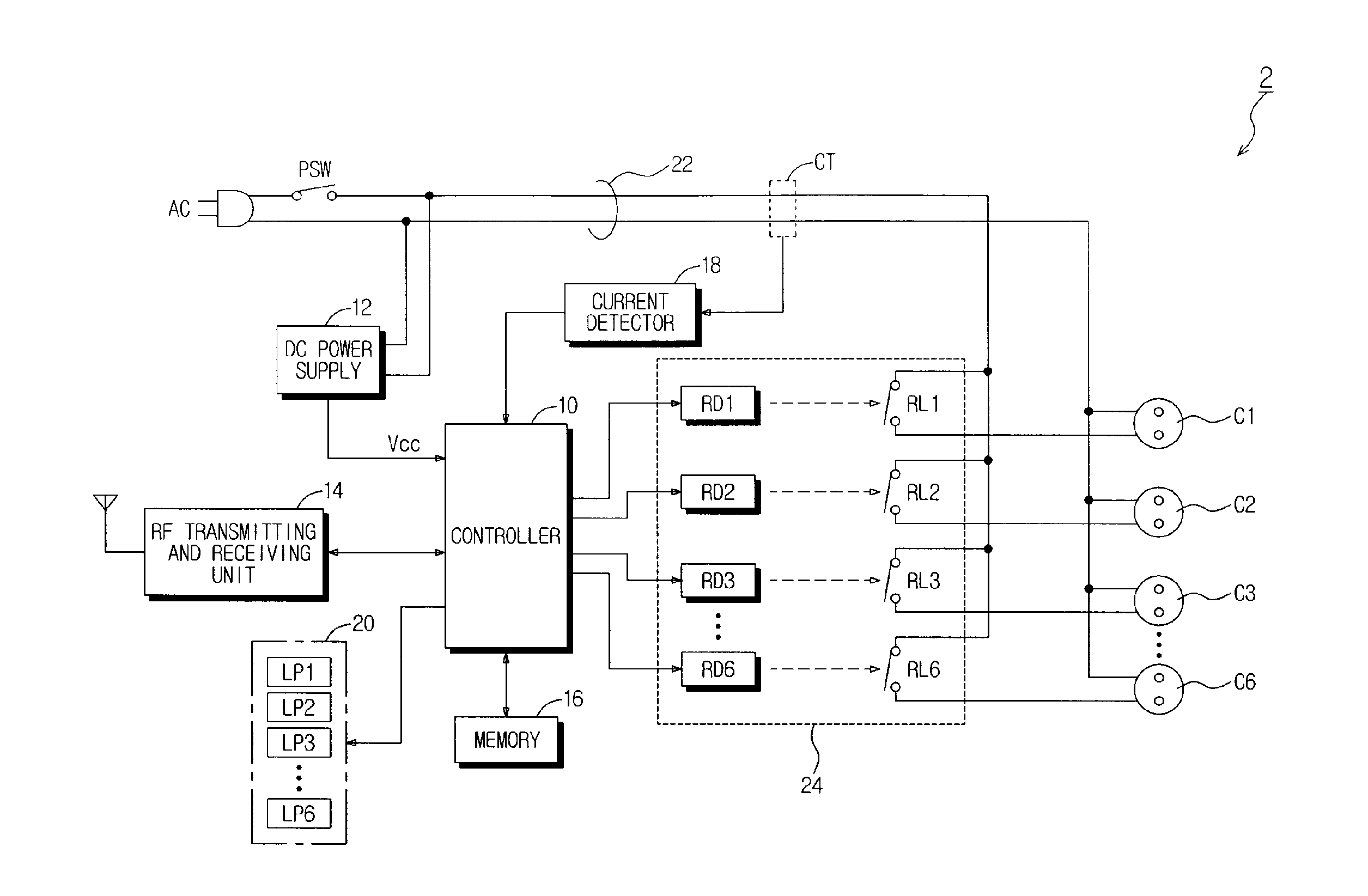
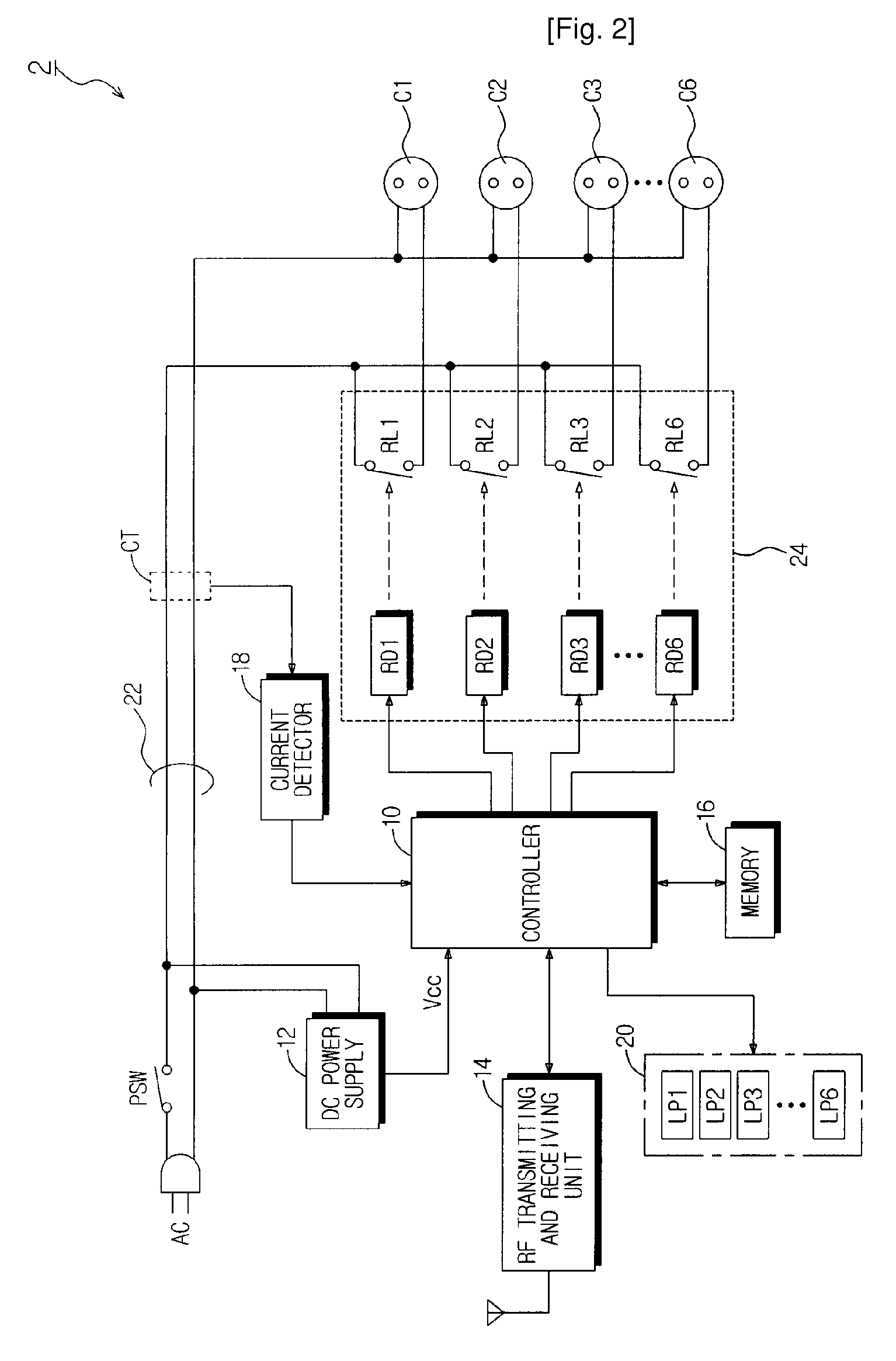
[0012]As described above, according to the present invention, outlets of a body of a power strip can be individually controlled to supply electric power by a user and electric power can be continuously supplied to an electric product that must be powered with priority while preventing overload when the overload is generated in a body of the power strip. Moreover, operating statuses of individually controlled connecting sockets of the power strip or operating status of a plurality of intermediate sockets connected to respective outlets can be remotely monitored.

Problems solved by technology

Thus, the power strip has a risk of overload all the time.
Since the plugs of the electric products are always inserted into the outlets, electric current is applied to the inactive electric products and thus unnecessary current is consumed.
In order to prevent this, although a power strip having switches installed in respective electric outlets has been developed such that a user can turn the switches on or off individually, it is very bothersome for the user to turn on / off the switches of the respective outlets one by one.

Method used


Image

  • Power-Controllable Outlet Receptacle
  • Power-Controllable Outlet Receptacle
  • Power-Controllable Outlet Receptacle

Examples


Embodiment Construction

[0024]Hereinafter, embodiments of the present invention will be described with reference to the accompanying drawings. It should be pointed out that the same numerals in the drawings are assigned to the same components. Moreover, the description for the conventional function and structure that may confuse spirit of the present invention will be omitted.

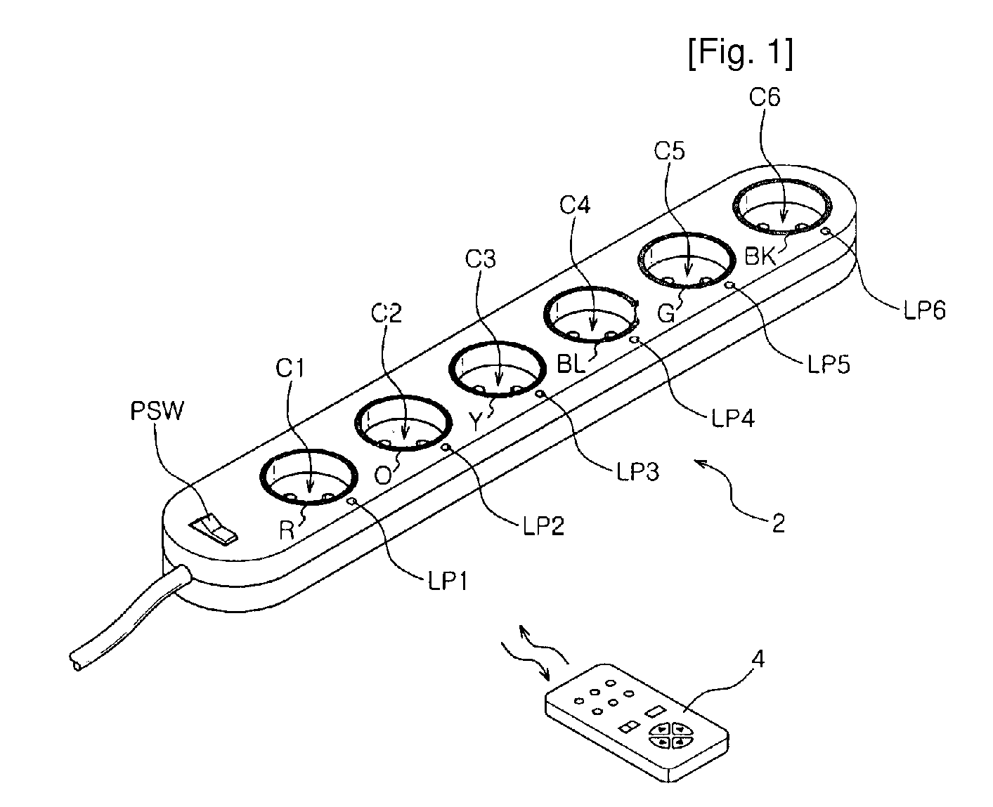
[0025]A power strip illustrated in FIGS. 1 to 5 relates to a multi-type power strip having multiple outlets according to an embodiment of the present invention, and a power strip illustrated in FIGS. 6 to 11 relates to an intermediate type power strip according to another embodiment of the present invention.

[0026]Firstly, the multi-type power strip according to the embodiment of the present invention will be described in detail with reference to FIGS. 1 to 5.

[0027]FIG. 1 illustrates a view illustrating an external appearance of the power-controllable multi-type power strip according to an embodiment of the present invention and the po...


PUM


Abstract

A multi-type power strip includes a main body having connecting sockets with surfaces indicated by priority of supplying electric power to the connecting sockets, operation lamps, and an electric circuit installed in the main body. The circuit interfaces with a remote controller through RF, and checks statuses of loads connected to the main body to switch plural switches based on the priority when the load exceeds a threshold. An intermediate type power strip includes intermediate socket main bodies inserted into sockets and respectively having at least one connecting socket, and a remote controller to individually control the intermediate socket main bodies in remote through RF communication. The surfaces of the intermediate socket main bodies are distinguished by indicators. When switch status of the intermediate socket main bodies is requested by the remote controller, the status is displayed by lamps of a socket controlling button of the remote controller.

Description

TECHNICAL FIELD[0001]The present invention relates to a power control apparatus, and more particularly, to method and an outlet receptacle capable of controlling electric power.BACKGROUND ART[0002]Electrical receptacles are commonly used in offices and homes. When an electric product requiring electric power such as a computer, a home appliance, an electric heater, a kitchen apparatus, and the like is remote from a main wall socket installed in a wall, a power strip is widely used to connect the electric product to the power source.[0003]The power strip includes a plurality of electrical outlets such that many electric plugs are inserted into the electrical outlet to use the plural electric products. Thus, the power strip has a risk of overload all the time. Since the plugs of the electric products are always inserted into the outlets, electric current is applied to the inactive electric products and thus unnecessary current is consumed.[0004]In order to prevent this, although a pow...

Claims


Application Information

Patent Timeline
Patent Type & Authority Applications(United States)
IPC IPC(8): H02J3/00H01H47/00
CPCH01R13/6641H01R13/7038H01R25/003H01R31/065
Inventor LIM, SEONG-KYU
Owner LIM CO LTD
Learn More