Vehicle control system

a control system and vehicle technology, applied in underwater vessels, special data processing applications, non-deflectable wheel steering, etc., can solve the problems of long time of vehicle out of operation and high resulting cost, and achieve the effect of reducing or disappearing vibration, facilitating technical implementation, and facilitating movemen

Active Publication Date: 2009-06-04
DEERE & CO
View PDF18 Cites 45 Cited by
  • Summary
  • Abstract
  • Description
  • Claims
  • Application Information

AI Technical Summary

Benefits of technology

[0009]According to the invention, operation of the vehicle may be simplified and optimized if an operating state which is unsafe or not optimal is not displayed to the operator merely by visual display instruments. Conventionally, the vehicle has a tachometer for displaying the engine speed. If the engine is continuously operated at an increased speed which is above the maximum speed provided for continuous operation, with a conventional vehicle there is no further indication, apart from increased noise generation of the engine, which with a relatively well sound-insulated cab of the vehicle may not be perceived acoustically in all cases. This may lead to engine damage and thus to a longer period of the vehicle being out of operation and thus to high resulting costs. According to the invention, it is therefore provided that optionally the operator is made aware in a tactile manner of such an operating state of the vehicle via an acoustic and / or visual warning device. This is advantageous, in particular, when the operator as a result of the situation has to react immediately in any manner, in order for example to be able to prevent an overload of a component of the vehicle or an accident to the vehicle.
[0013]The control unit, depending on the current operating state of the vehicle, controls the adjusting device so that the steering wheel may be acted upon by an altered predetermined force, in order to make the operator aware of an unsafe operating state of the vehicle or an unsafe operating state of at least one operating function.
[0037]Preferably, the level of force at which the steering wheel may be acted upon, may be individually set by the operator. As a result, for example, each operator is able to set and / or possibly store an individually adapted operating characteristic of the steering wheel. This allows an adjustment of the steering wheel characteristic adapted individually thereto and may thus avoid faulty operation and / or allow individual ergonomic operation.
[0042]It could be provided that the force exerted by the adjusting device on the steering wheel may be overridden and / or switched off by the operator. An overriding of the force exerted on the steering wheel by the operator should generally be possible, as it is not only intended that the operator feels that he / she has control over the operation of the vehicle. In addition, for safety reasons, the vehicle is also intended to be able to be operated by the operator if the steering wheel is acted upon by an incorrect force. This could be the case if a sensor detects a variable in error or the detected variable is interpreted incorrectly, although the probability of this occurring is only low. To this extent, the possibility of overriding a force which is exerted on the steering wheel represents a comparable possibility which a vehicle operator has with a navigation unit. There too, the operator can decide whether he selects the route which is proposed by the navigation unit or another route.

Problems solved by technology

If the engine is continuously operated at an increased speed which is above the maximum speed provided for continuous operation, with a conventional vehicle there is no further indication, apart from increased noise generation of the engine, which with a relatively well sound-insulated cab of the vehicle may not be perceived acoustically in all cases.
This may lead to engine damage and thus to a longer period of the vehicle being out of operation and thus to high resulting costs.

Method used


Image

  • Vehicle control system
  • Vehicle control system
  • Vehicle control system

Examples


Embodiment Construction

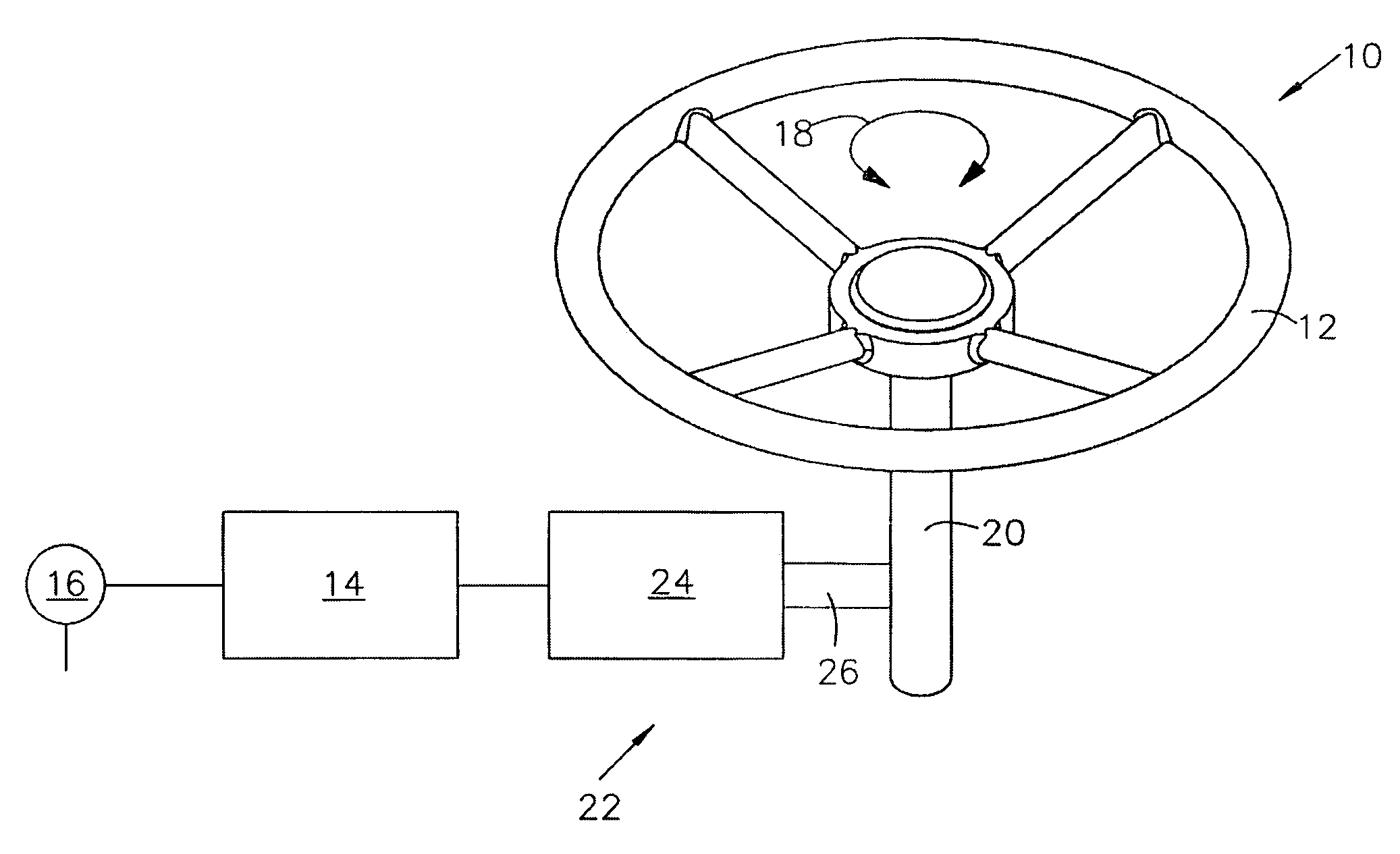
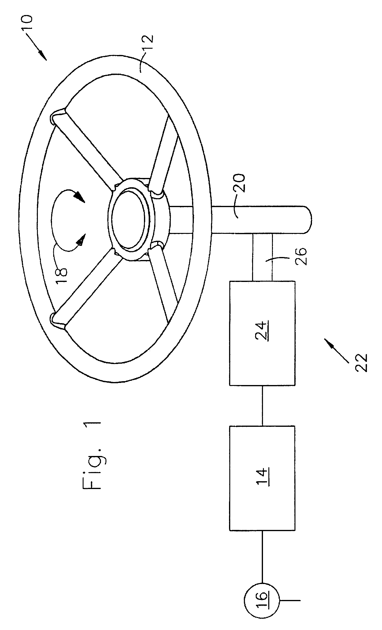
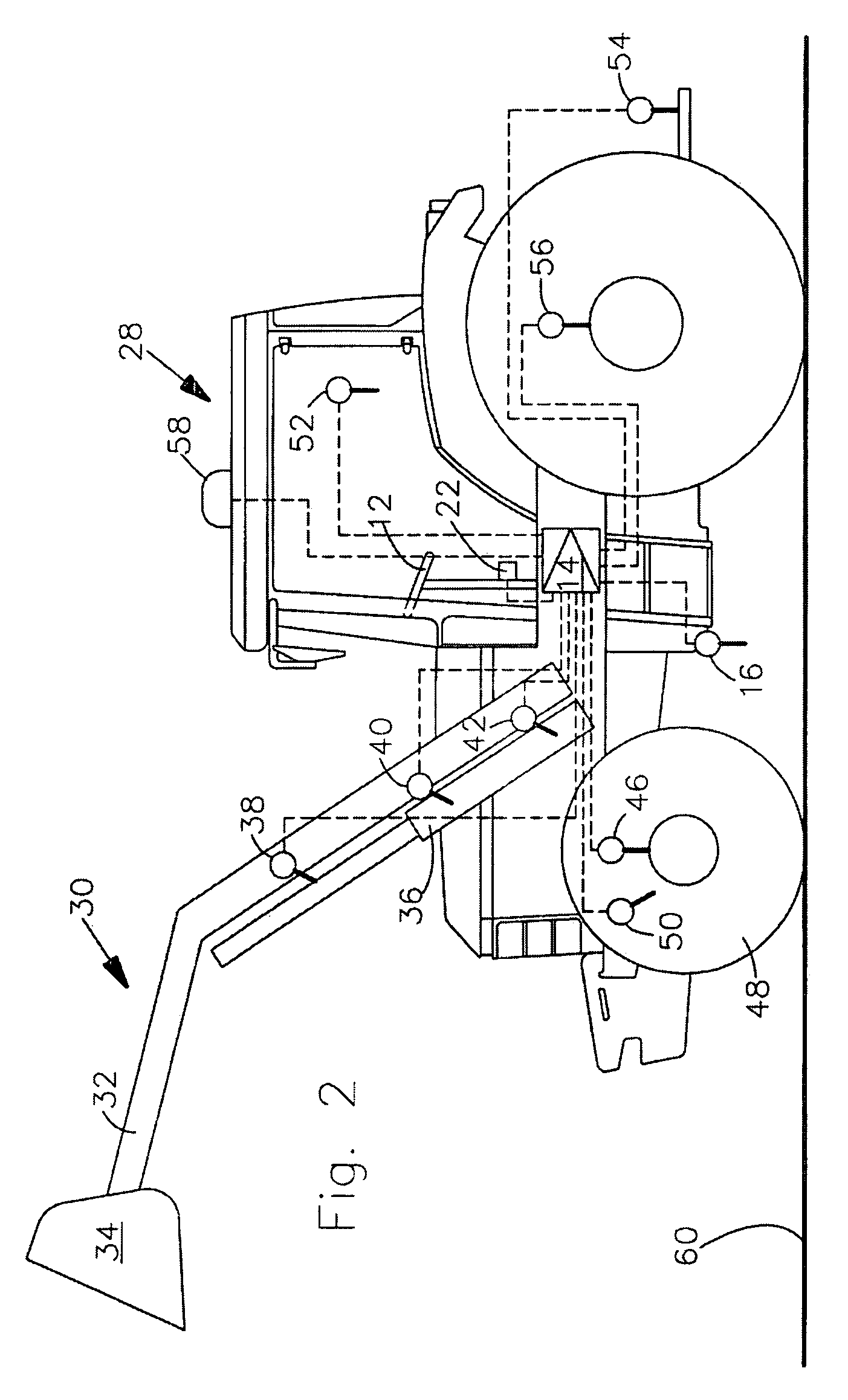
[0058]Referring to FIG. 1, the control system 10 has a steering wheel 12, a shaft or steering column 20, a control unit 14 and a sensor 16. The steering wheel 12 may be pivoted about the axis of shaft 20 in the direction of the double arrow 18. The control system 10 controls the travel direction of the agricultural vehicle or tractor shown in FIG. 2.

[0059]The control system 10 also includes an adjusting device 22, which comprises an actuator 24. The actuator 24 has an electric motor, which may be controlled by the control unit 14 via a power electronics unit (not shown). A gear train 26 transmits the torque produced by the electric motor to the steering column 20. The actuator 24 acts via the gear train 26 on the steering wheel 12 with a torque which may act in an clockwise direction or in an anticlockwise direction.

[0060]A sensor (not shown) on the actuator 24 senses the current position of the steering wheel 12 and transmits a sensor signal to the control unit 14. The sensor 16 de...


PUM


Abstract

A vehicle control system includes a steering wheel, such as an steering wheel, an adjusting device, a sensor and a control unit. The steering wheel may be actuated by the hand of an operator to set a state variable of the vehicle. The adjusting device applies a force to the steering wheel. A sensor senses a variable representing a state variable of the vehicle and transmits a sensor signal to the control unit. The control unit determines a state variable of the current operating state of the vehicle. The control unit, depending on the current operating state of the vehicle, controls the adjusting device so that a predetermined force is applied to the steering wheel, in order to make the operator aware of an unsafe operating condition.

Description

FIELD OF THE INVENTION[0001]The present invention relates to a control system for a vehicle.BACKGROUND OF THE INVENTION[0002]Manually operated steering wheels are used to control the travel direction of vehicles.[0003]Moreover, force-feedback is known from the field of simulator technology and is used to realistically represent forces on operating elements, which occur during the operation of machines and which must be applied and / or overcome by the operator.[0004]In many vehicles, the operating elements are mechanically connected to a machine part. For example, the steering wheel is connected by a steering shaft to the steering gear. If such a mechanical connection is omitted due to an electronic control of the respective component, a corresponding feedback about the conditions of the machine part and the machine / vehicle to be simulated is not provided to the operator. In such a case, the technology known from simulator technology is utilized, namely by the operating element or ste...

Claims


Application Information

Patent Timeline
Patent Type & Authority Applications(United States)
IPC IPC(8): B62D6/00
CPCA01D41/127A01D75/18B60Q9/00B60W10/20B60Y2200/41B60W40/1005B60W50/16B60W2040/1307B60W40/06B60K2370/158B60Q2800/20
Inventor TARASINSKI, NICOLAIHAHN, KLAUS
Owner DEERE & CO
Why Eureka
Try Eureka