Fluid ejecting apparatus and method for controlling driving of caps

a technology of ejecting apparatus and cap, which is applied in the direction of printing, other printing apparatus, etc., can solve the problems of interior staining, and achieve the effect of accurately and efficiently capturing ejecting liquid, accurately and efficiently capping the head area, and accurate and efficient capping

Inactive Publication Date: 2008-12-18
SEIKO EPSON CORP
View PDF3 Cites 47 Cited by
  • Summary
  • Abstract
  • Description
  • Claims
  • Application Information

AI Technical Summary

Benefits of technology

[0010]One aspect of the invention is a liquid ejecting apparatus comprising a liquid ejecting head capable of ejecting liquid and a plurality of cap units each having a cap for individually capping a plurality of head areas of the liquid ejecting head. The plurality of cap units are constructed such that the shift position of each cap can be varied in order to more accurately cap the head area, regardless of the distortion of the liquid ejecting head.
[0011]Using this structure, the caps can be brought into close contact with the corresponding head areas with substantially uniform and appropriate strength when the caps are moved to the capping positions. Thus, embodiments of the present invention are capable of capping the head areas more effectively than the capping mechanisms currently known in the art. When the caps are moved to the capping positions, the caps can be disposed in appropriate flushing positions a predetermined distance from the corresponding head areas This allows the caps to more accurately and efficiently capture the ejected liquid (drops).
[0012]Advantageously, this alleviates the staining of the interior of the liquid ejecting apparatus due to a mist of the drops that are not collected by the capping mechanism because the gaps between the nozzle surface and capping mechanism are excessively wide. In addition, embodiments of the present invention also prevent the any ink from rebounding from the caps and onto the head areas because the space between the caps and head areas is excessively narrow.
[0013]The shift-position data includes not only position data for use in determining shift positions but also moving-distance data for use in determining shift positions. This also applies to the following:
[0014]In this case, the controller controls the driving of the power source according to the shift-position data read from the memory. As a result, the caps can be disposed in appropriate shift positions according to the distortion of the liquid ejecting head. This reduces variations in the relative positions of the caps and the head areas.
[0015]With this arrangement, even if the liquid ejecting head is deflected across the length because of its own weight or a tightening force during assembly, the cap shift positions can be adjusted individually so as to compensate for the distortion. Thus, the caps can be moved to the shift positions so as to maintain a fixed position relationship relative to the liquid ejecting head.

Problems solved by technology

Advantageously, this alleviates the staining of the interior of the liquid ejecting apparatus due to a mist of the drops that are not collected by the capping mechanism because the gaps between the nozzle surface and capping mechanism are excessively wide.

Method used


Image

  • Fluid ejecting apparatus and method for controlling driving of caps
  • Fluid ejecting apparatus and method for controlling driving of caps
  • Fluid ejecting apparatus and method for controlling driving of caps

Examples


first embodiment

[0032]A first embodiment of the invention will be described herein with reference to FIGS. 1 to 7.

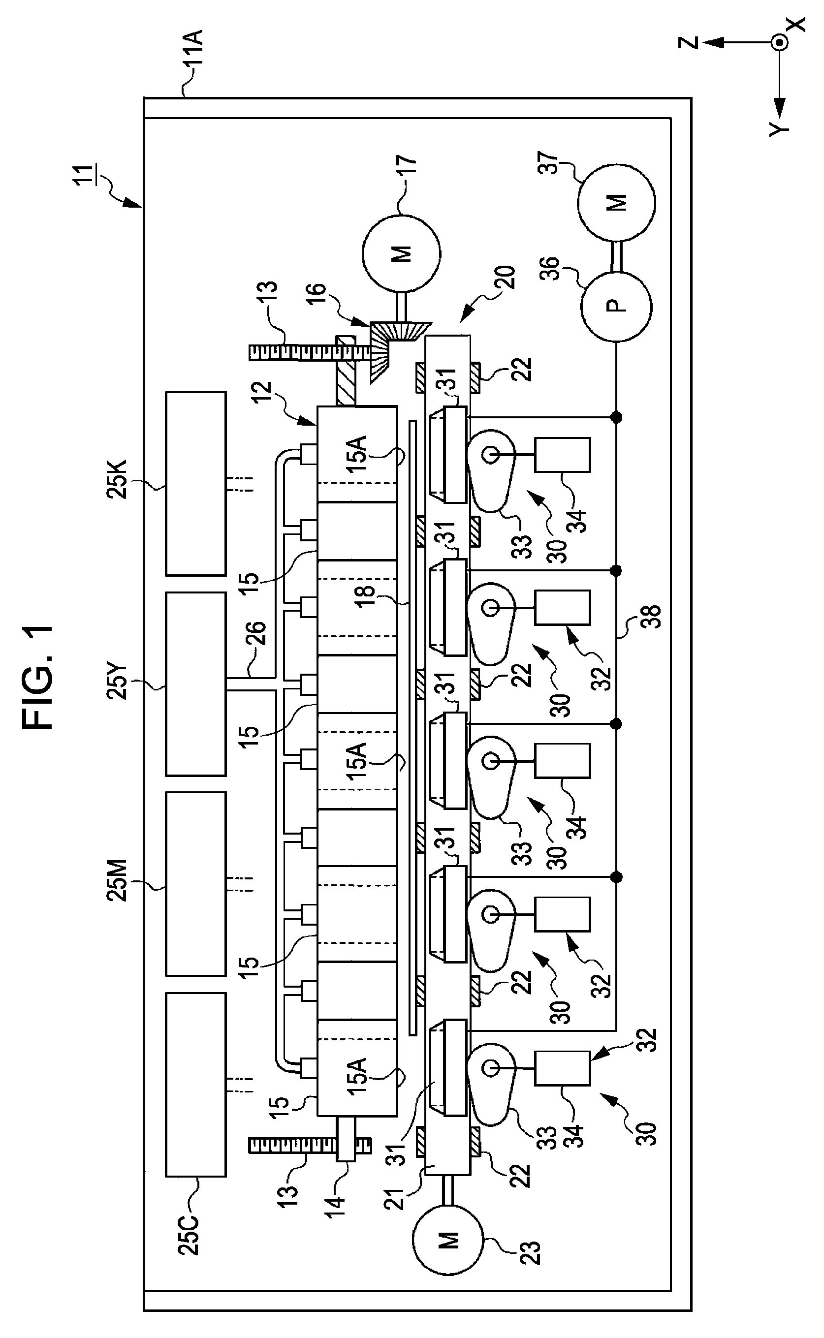
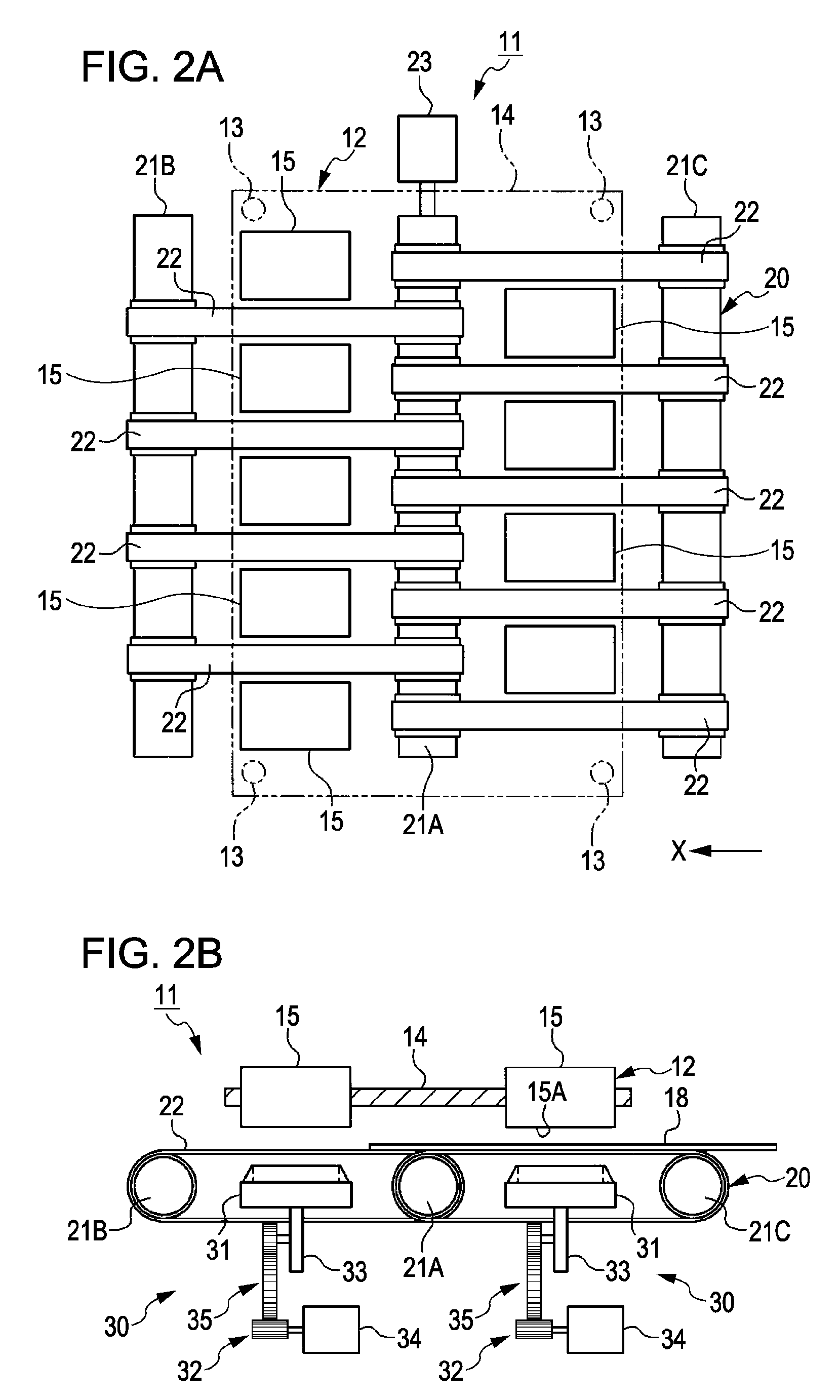
[0033]FIG. 1 is a schematic sectional view of an ink jet recording apparatus, which represents an exemplary embodiment of a liquid ejecting apparatus which may be used in association with the present invention. FIG. 2A is a plan view of the ink jet recording apparatus, and FIG. 2B is a side view of the same. FIGS. 2A and 2B omit a diagram of the ink supply system, including the ink cartridge.

[0034]As shown in FIGS. 1 and 2, in this example the ink jet recording apparatus (hereinafter, simply referred to as a printer 11) is a line printer having a line head 12 which acts as a liquid ejecting head, which extends across the entire maximum paper width. Depending on the specific configuration of the printer, in this example, four erect driving shafts 13 (two are shown in FIG. 1) are disposed in a box body case 11A which has an open top. A head support member 14 acts as a support frame, and i...

second embodiment

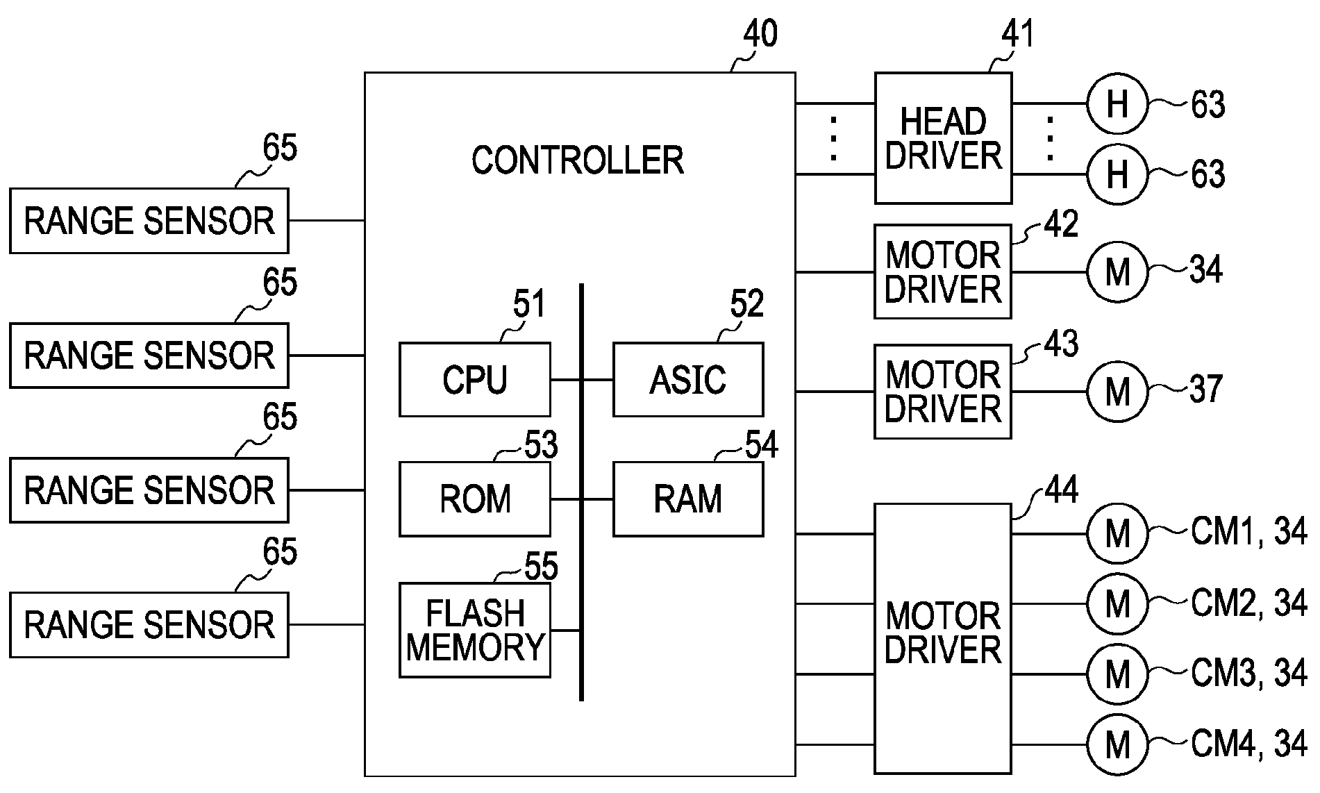
[0060]A second embodiment of the invention may be described using another printer as an example. The printer includes including a range sensor for measuring the distance between nozzle surface and caps. FIG. 9A is a bottom view of the line head as viewed from the nozzle surface FIG. 9B is a schematic front view of the printer. FIG. 9B shows an example in which a line head 61 warps.

[0061]As shown in FIG. 9A, the line head 61 includes a long-rectangular-plate head support member 62 and a plurality of record heads 63, which are head areas or unit heads that are embedded in the head support member 62. The nozzle surfaces 63A of the record heads 63 each have a plurality of nozzle trains 63B (four, in this example) which correspond to the colors of ink (which is also four in this example). The nozzle trains 63B of the same color of the record heads 63 communicate with one another through the same channel in the head support member 62. The record heads 63 are arranged such that the nozzle ...

first modification

[0077]The cap moving distance may not necessarily be varied. In other words, the shift positions, including the capping positions and the flushing positions need only to be changed according to the distortion of the line head. For example, another structure may be adopted in which the retracted positions, or lowermost positions, of the caps are adjusted according to the distortion of the line head wherein the cap shift positions are adjusted according to the distortion of the line head by setting the travel strokes of the caps from the retracted positions to the capping positions or the flushing position to the same value for any cap.


PUM


Abstract

There is provided a liquid ejecting apparatus including: a liquid ejecting head capable of ejecting liquid; and a plurality of cap units each having a cap for individually capping a plurality of head areas of the liquid ejecting head. The plurality of cap units is constructed such that the shift position of each cap that is shifted from a retracted position toward the head area can be varied according to the distortion of the liquid ejecting head.

Description

BACKGROUND[0001]The entire disclosure of Japanese Patent Application No. 2007-155211, filed Jun. 12, 2007 is expressly incorporated herein by reference.[0002]1. Technical Field[0003]The present invention relates to a fluid or liquid ejecting apparatus. More specifically, the present invention relates to a liquid ejecting apparatus including a cap unit for capping a liquid ejecting head and a method for controlling the driving of the caps.[0004]2. Related Art[0005]One example of a liquid ejecting apparatus that is currently known in the art is a printer, such as those disclosed in Japanese Patent JP-A-2007-69448 (as described in paragraphs [0050] and [0051] and FIGS. 7 and 8) and Japanese Patent JP-A-2005-67127 (as described in paragraph and FIGS. 2B and 12). The printers disclosed in the are line printers (line ink-jet recording apparatuses) which include a plurality of staggered record heads disposed between a plurality of transport belts. There is a plurality of cap units (head re...

Claims


Application Information

Patent Timeline
Patent Type & Authority Applications(United States)
IPC IPC(8): B41J29/393B41J2/165
CPCB41J2/16511B41J2/16585B41J29/38
Inventor TAKAHASHI, NOBUHITO
Owner SEIKO EPSON CORP
Why Eureka
Try Eureka