Developing roller specific for mono-component developing apparatus

a developing roller and mono-component technology, applied in electrographic process equipment, instruments, optics, etc., can solve problems such as insufficient toner leakage prevention, problem raised, and toner leakage, and achieve the effect of preventing toner leakage and scarcely increasing the driving torque of the developing roller

Active Publication Date: 2008-12-18
KONICA MINOLTA BUSINESS TECH INC
View PDF0 Cites 9 Cited by
  • Summary
  • Abstract
  • Description
  • Claims
  • Application Information

AI Technical Summary

Benefits of technology

[0009]The objective of the present invention is to provide a developing roller which makes it possible to sufficiently prevent toner leakage, with the driving torque of the developing roller being scarcely increased, and a mono-component developing apparatus having such a developing roller.

Problems solved by technology

In the mono-component developing apparatus, upon transporting the toner to a developing area by the rotation of the developing roller, different from the two-component developing apparatus, no magnetic force can be utilized, and since the toner is not sufficiently held, a problem arises in which toner leakage occurs due to toner movements toward the developing-roller axis direction.
However, toner is intruded into a gap between each of the two end portions of the developing roller and the sealing member to cause toner fusion, failing to sufficiently prevent toner leakage.
However, in the above-mentioned developing roller, since the adhesion between the developing roller and the sealing member become high, a new problem is raised in which the driving torque of the developing roller is raised extremely.

Method used


Image

  • Developing roller specific for mono-component developing apparatus
  • Developing roller specific for mono-component developing apparatus
  • Developing roller specific for mono-component developing apparatus

Examples


example a

Blasting Process

Examples / Comparative Examples

Production of Developing Roller

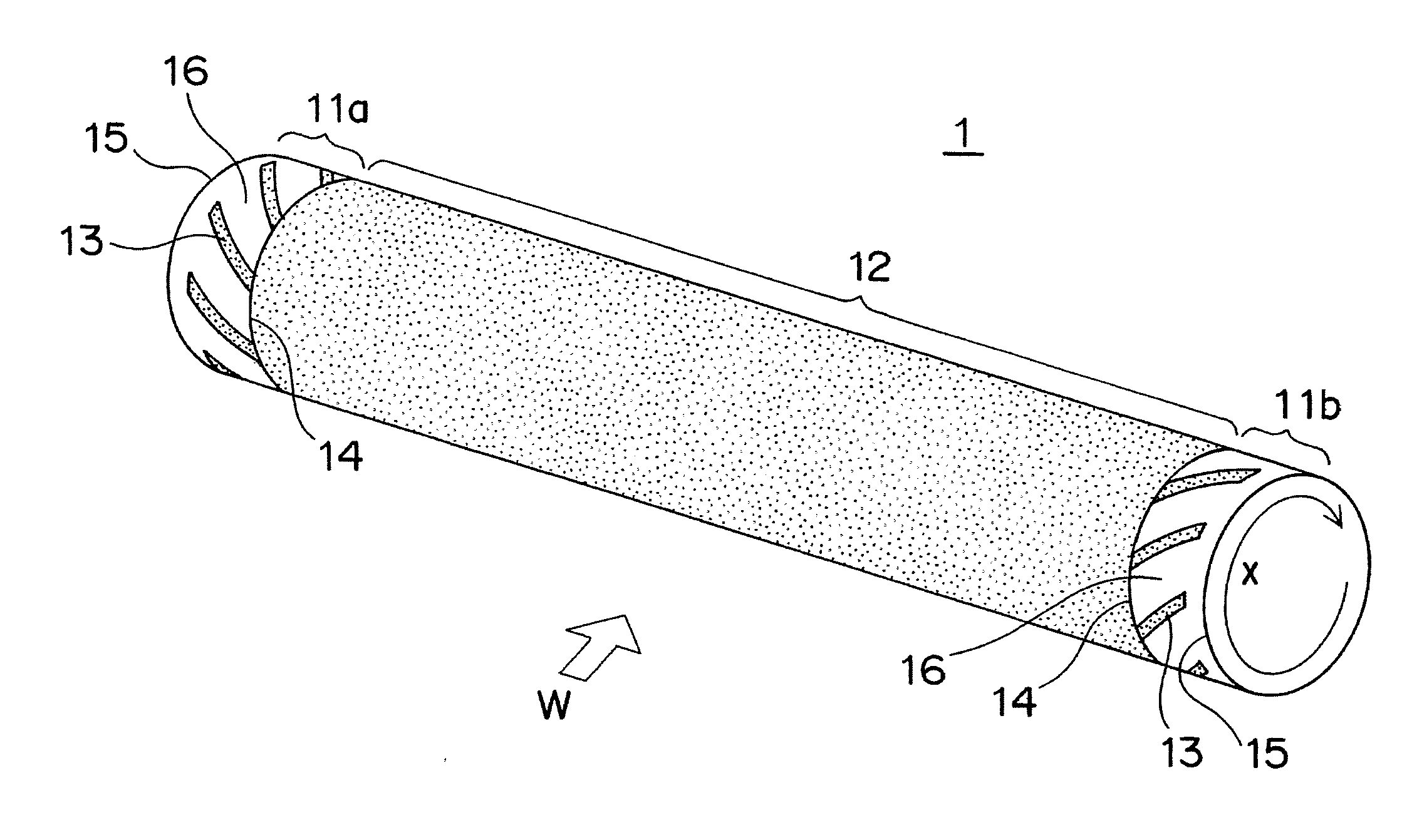
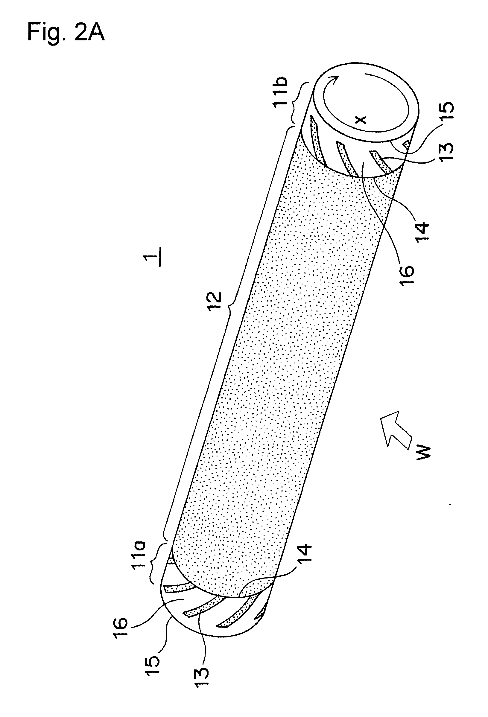
[0055]A center portion 12 and two end portions 11a and 11b of the outer surface of each of core metal shafts, made of aluminum, having an outer diameter of 16 mm (236.8 mm in length in the axis direction) were subjected to blasting treatments by using a mask. As a result, each of developing rollers, which has blast-treated areas having a spiral shape on its circumferential face of each of the two end portions, with a blast-treated area serving as a toner transporting area being formed on the circumferential face of the center portion, was obtained. Each of the developing rollers had the same overall shape as the shape shown in FIG. 2, except that the spiral shape of the surface processing areas 13 thereof was different. The surface shape, dimension and the like of the respective portions are shown in the Table. In any of the developing rollers, the other area 16 in each of the two end portions 11a and 11b ha...

experimental example b

Resin Coating Treatment

Examples / Comparative Examples

Production of Developing Roller

[0064]A center portion 12 and two end portions 11a and 11b of the outer surface of each of core metal shafts, made of iron, having an outer diameter of 16 mm (236.8 mm in length in the axis direction) were subjected to resin coating treatments by using a mask. As a result, each of developing rollers, which has resin-coated areas having a spiral shape on its circumferential face of each of the two end portions, with a resin-coated area serving as a toner transporting area being formed on the circumferential face of the center portion, was obtained. Each of the developing rollers had the same overall shape as the shape shown in FIG. 2, except that the spiral shape of the surface processing areas 13 thereof was different. The surface shape, dimension and the like of the respective portions are shown in the Table. In any of the developing rollers, the other area 16 in each of the two end portions 11a and ...


PUM


Abstract

To provide a developing roller which makes it possible to sufficiently prevent toner leakage, with the driving torque of the developing roller being scarcely increased, and a mono-component developing apparatus having such a developing roller.A developing roller for a mono-component developing apparatus, which transports toner supported on an outer circumferential face of a center portion 12 toward a developing area by rotating while frictionally sliding on a sealing member on each of two end portions 11a, 11b, comprising:surface processing areas 13 having a spiral shape, placed on each of outer circumferential faces of the two end portions,wherein an angle θ, made by a spiral direction y of each surface processing area and the rotation direction x, is allowed to have an acute angle, and a mono-component developing apparatus having such a developing roller.

Description

[0001]This application is based on application(s) No. 2007-155025 filed in Japan, the contents of which are hereby incorporated by reference.BACKGROUND OF THE INVENTION[0002]1. Field of the Invention[0003]The present invention relates to a mono-component developing apparatus and a developing roller to be used in such a developing apparatus. In particular, the developing roller of the present invention is classified as a hard roller without a foamed material layer.[0004]2. Description of the Related Art[0005]In a mono-component developing apparatus, an electrostatic latent image on a latent-image-bearing member is visualized by using a mono-component developer made from toner, through an electro-photographic system. In a two-component developing apparatus, an electrostatic latent image is visualized by using a two-component developer made from toner and a carrier. In the mono-component developing apparatus, upon transporting the toner to a developing area by the rotation of the devel...

Claims


Application Information

Patent Timeline
Patent Type & Authority Applications(United States)
IPC IPC(8): G03G15/08
CPCG03G15/0818G03G15/0898
Inventor NISHIKAWA, TOMOHARUTANIGUCHI, TOSHIHIDESAKAI, TOSHIYUKIOKABE, NORIKAZUUENO, HIROMASA
Owner KONICA MINOLTA BUSINESS TECH INC
Why Eureka
Try Eureka