

Viscosity sensor
a technology of viscosity sensor and viscosity, applied in the field of viscosity sensor, can solve problems such as engine damag
- Summary
- Abstract
- Description
- Claims
- Application Information
AI Technical Summary
Benefits of technology
Problems solved by technology
Method used
Image

Examples
Embodiment Construction
[0014]The present invention is intended for application in automotive vehicle systems and will be described in that context. It is to be understood, however, that the present invention could also be successfully applied in many other applications including non-vehicle applications.
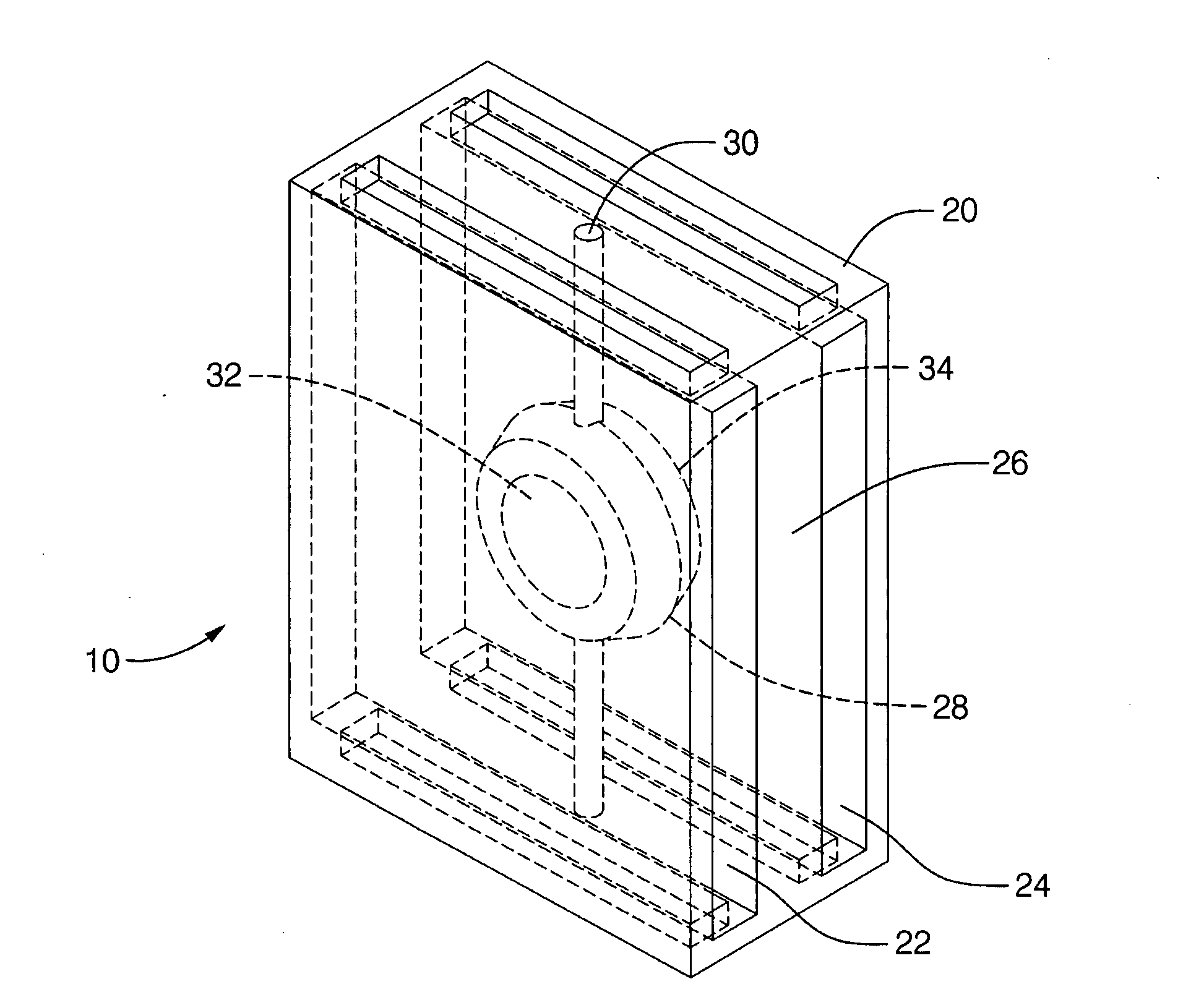
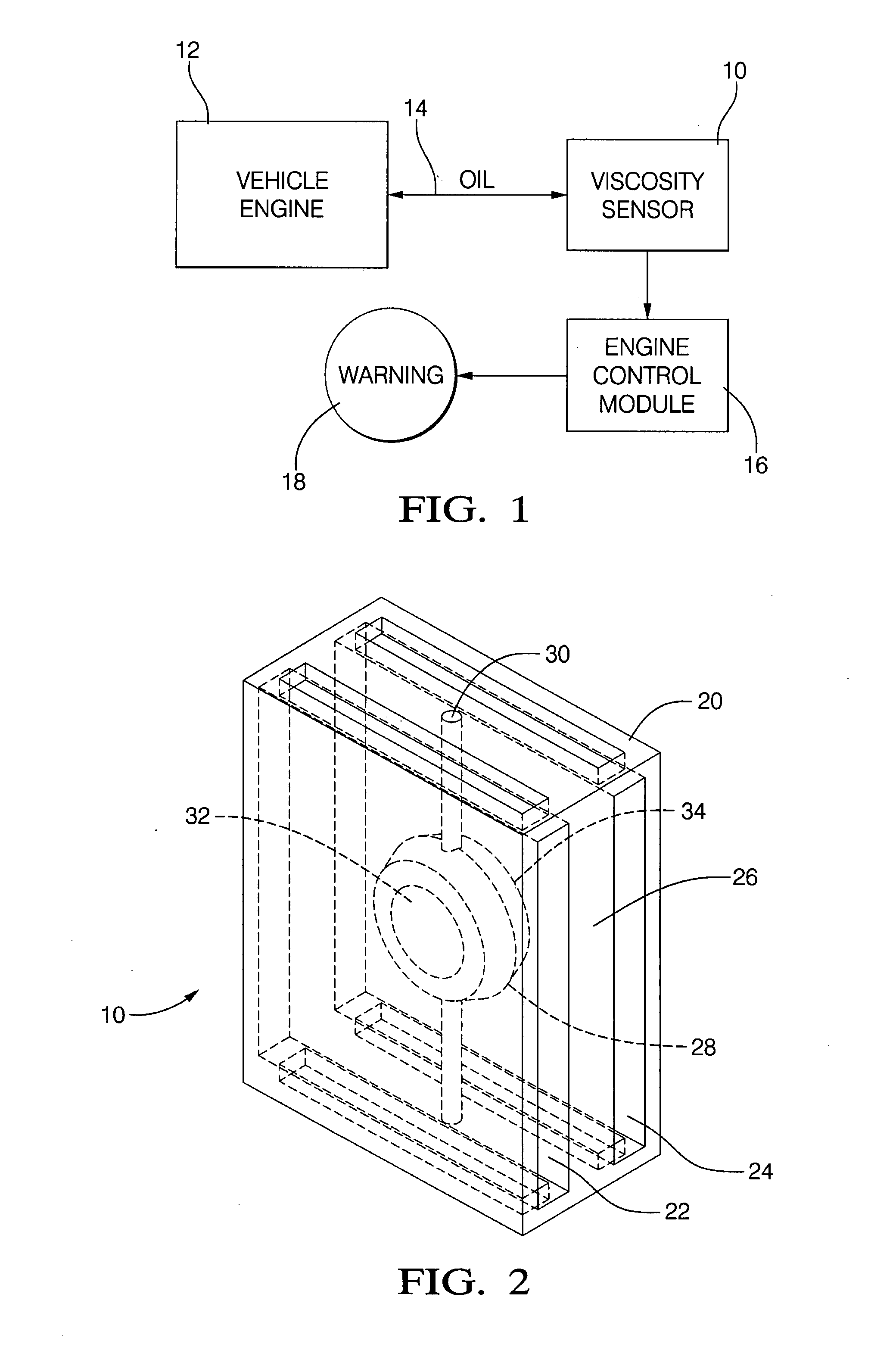
[0015]Referring initially to FIG. 1, a viscosity sensor 10 is shown which receives a fluid such as oil from a source such as a vehicle engine 12 through a fluid passage 14 for outputting a signal representative of the viscosity of the fluid in accordance with principles set forth further below. In the vehicle application, the sensor 10 may output an electrical signal to a computer such as an engine control module 16 that can process the signal and, if the signal indicates that the oil viscosity is not in a predetermined viscosity range, actuate a warning element 18 such as a lamp and / or an audio or visual message indicating a viscosity fault. The sensor 10 when used in the vehicle application may be mounte...
PUM
| Property | Measurement | Unit |
|---|---|---|
| frequency | aaaaa | aaaaa |
| viscosity | aaaaa | aaaaa |
| frequency | aaaaa | aaaaa |
Abstract
Description
Claims
Application Information