Method of fabricating a micromachined tube for fluid flow

a micromachined tube and fluid flow technology, applied in the direction of liquid/fluent solid measurement, instruments, specific gravity measurement, etc., can solve the problems of large size and high cost, and achieve the effect of high aspect ratio etching techniques

Inactive Publication Date: 2005-08-30
INTEGRATED SENSING SYST INC
View PDF5 Cites 42 Cited by
  • Summary
  • Abstract
  • Description
  • Claims
  • Application Information

AI Technical Summary

Benefits of technology

[0009]Three preferred methods of fabricating micromachined fluidic apparatus for the detection of fluid flow, density and viscosity are also disclosed. The first preferred method utilizes selective etching, boron-doped silicon and silicon fusing bonding to achieve a free-standing micromachined tube section on an insulating substrate. A second preferred method utilizes a buried silicon dioxide layer or doped silicon layers, to create etch stops, with high aspect ratio etching techniques and silicon fusing bonding being used to create a free-standing micromachined tube system, al

Problems solved by technology

Their major shortcomings ar

Method used


Image

  • Method of fabricating a micromachined tube for fluid flow
  • Method of fabricating a micromachined tube for fluid flow
  • Method of fabricating a micromachined tube for fluid flow

Examples


Embodiment Construction

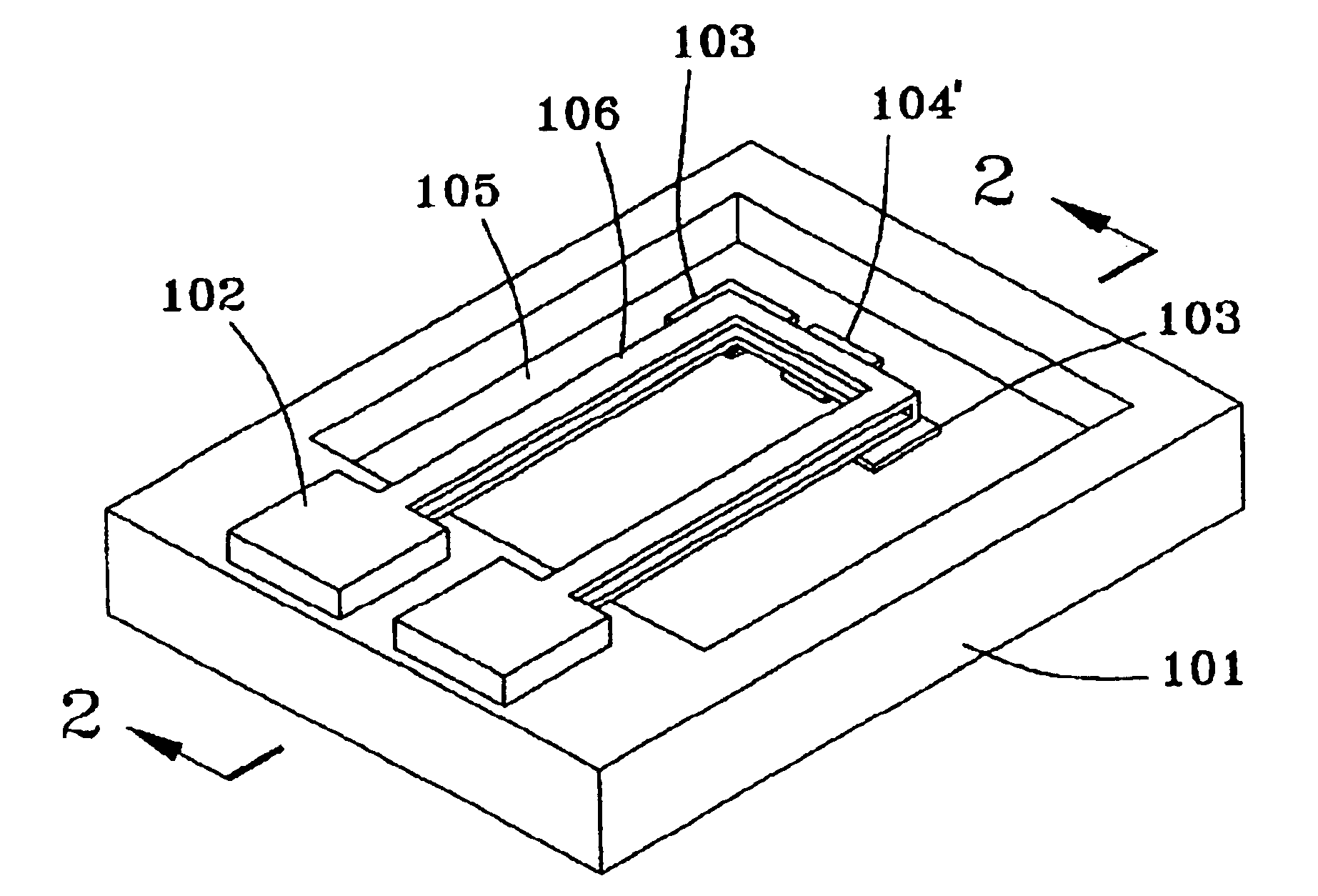
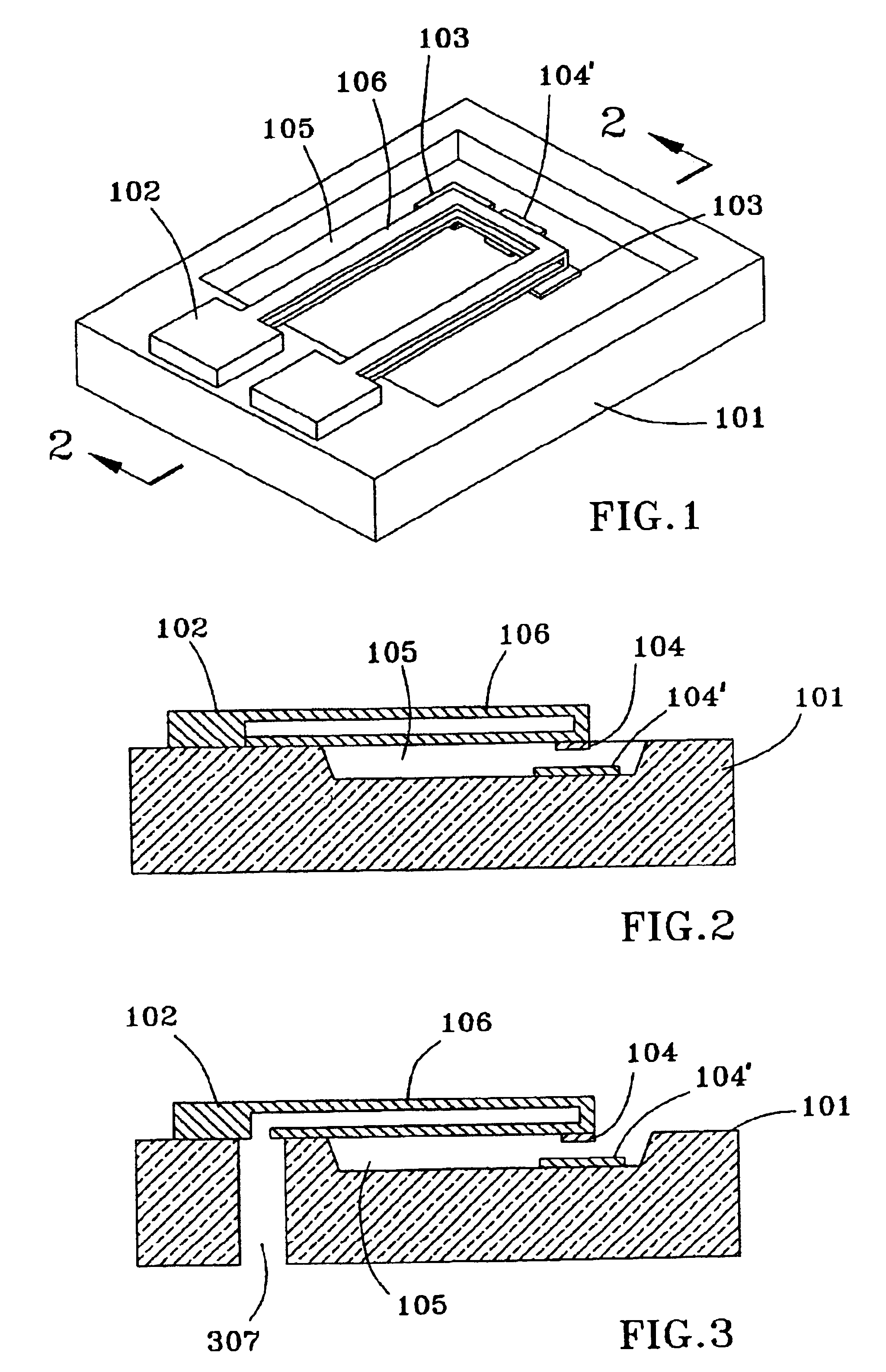
[0024]FIGS. 1 and 2 depict micromachined fluidic apparatus according to the invention. The system includes a substrate 101 to which there is attached a micromachined tube system 102. In the embodiment shown, a portion of the tube system 102 is attached to the top surface of the substrate 101 while the rest of the tube system is suspended above the substrate, as shown, thereby creating a free-standing tube section 106.

[0025]The substrate 101 may be an electrical insulator, conductor, or a conductor with an insulating layer. For example, the substrate may be glass (e.g., Corning 7740), ceramic, plastic, metal, alloy, silicon, or silicon with a layer of silicon oxide or silicon nitride on top. The tube system 102 may be attached to the substrate using a variety of techniques, including, but not limited to, anodic bonding, fusion bonding, eutectic bonding, thermal bonding, glass frit bonding, compression bonding, and thermal compression bonding. Note there is a gap 105 between the free-...


PUM

PropertyMeasurementUnit
Viscosityaaaaaaaaaa
Densityaaaaaaaaaa
Ratioaaaaaaaaaa

Abstract

Micromachine fluidic apparatus incorporates a free-standing tube section and electrodes to actuate or control the movement of the tube section, or to sense the movement of the tube section, or both. Electronic circuitry, which may be disposed on the same substrate as the fluidic portion of the apparatus, is used in conjunction with the tube and electrodes in conjunction with a variety of different applications, including fluid flow measurement, fluid density measurement, fluid viscosity measurement, fluid transport, separation and/or mixing. According to a particular embodiment, the free-standing section of the tube is resonated for fluid flow and density measurements according to the Coriolis effect. Capacitive/electrostatic actuation techniques are used to control or resonate the free-standing section of the tube, and to detect variations in tube movement. Different methods of fabricating micromachine fluidic apparatus are also disclosed, including the use of fusion bonding of non-conducting substrates, high-aspect ratio etching techniques, and anisotropic etching and refill techniques, preferably utilizing chevron-shaped slit openings to fabricate microtube sections.

Description

[0001]This is a divisional of application Ser. No. 09 / 468,628, filed Dec. 21, 1999, now U.S. Pat. No. 6,477,901.[0002]This invention was made with U.S. Government support under SBIR Contract PAN RTW M4-97 awarded by the U.S. Army. The U.S. Government has certain rights in this invention.FIELD OF THE INVENTION[0003]This invention relates generally to micro-machined fluidic devices, including micro-fluidic apparatus, flow sensors, flow tubes, fluidic density sensors, flow controllers, chemical and biochemical systems, and the like, and, in particular, to the fabrication and implementation of flow measurement devices, fluid density measurement devices and fluidic circuits using silicon microfabrication and precision micromachining techniques.BACKGROUND OF THE INVENTION[0004]Fluid measurement, control and manipulation are very important in many applications. Direct, accurate on-line measurement of mass flow and fluid density has been made possible through the development of different ty...

Claims


Application Information

Patent Timeline
IPC IPC(8): G01F1/84G01F1/76G01N9/00
CPCG01F1/8404G01F1/8445G01F1/8472G01N9/002G01N11/16Y10T29/49995G01N2009/006Y10T29/49428Y10T29/49002
Inventor TADIGADAPA, SRINIVASTSAI, CHIALUNZHANG, YAFANNAJAFI, NADER
Owner INTEGRATED SENSING SYST INC
Why Eureka
Try Eureka