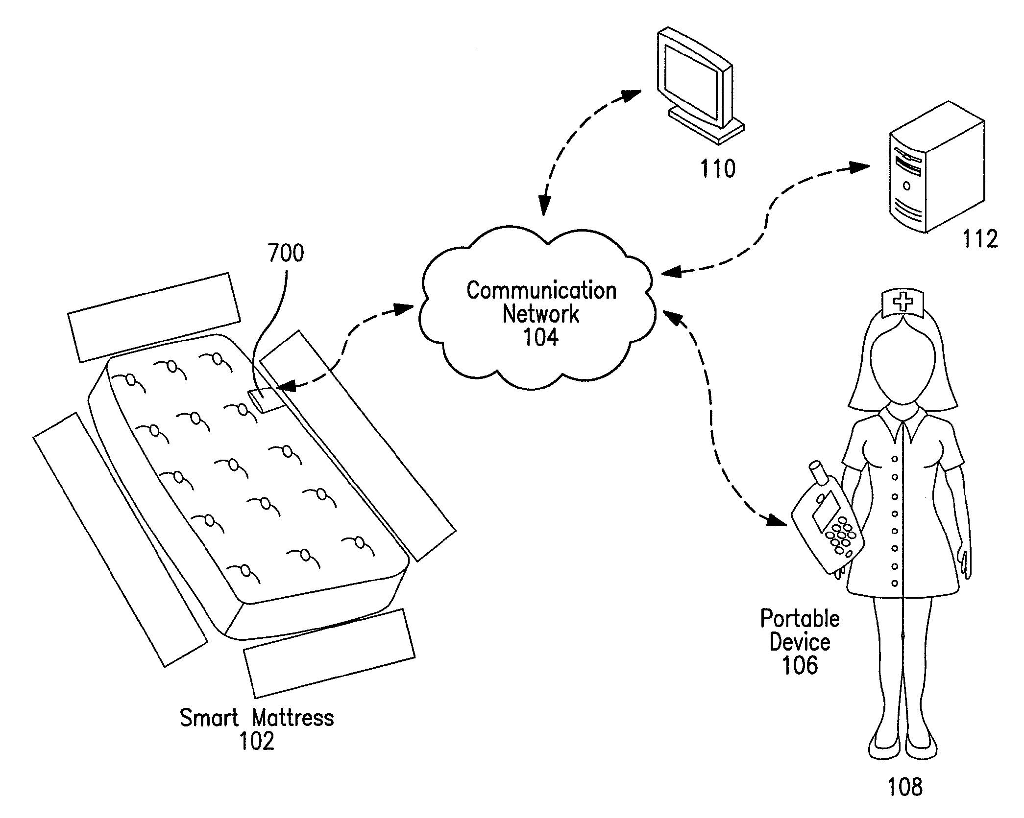
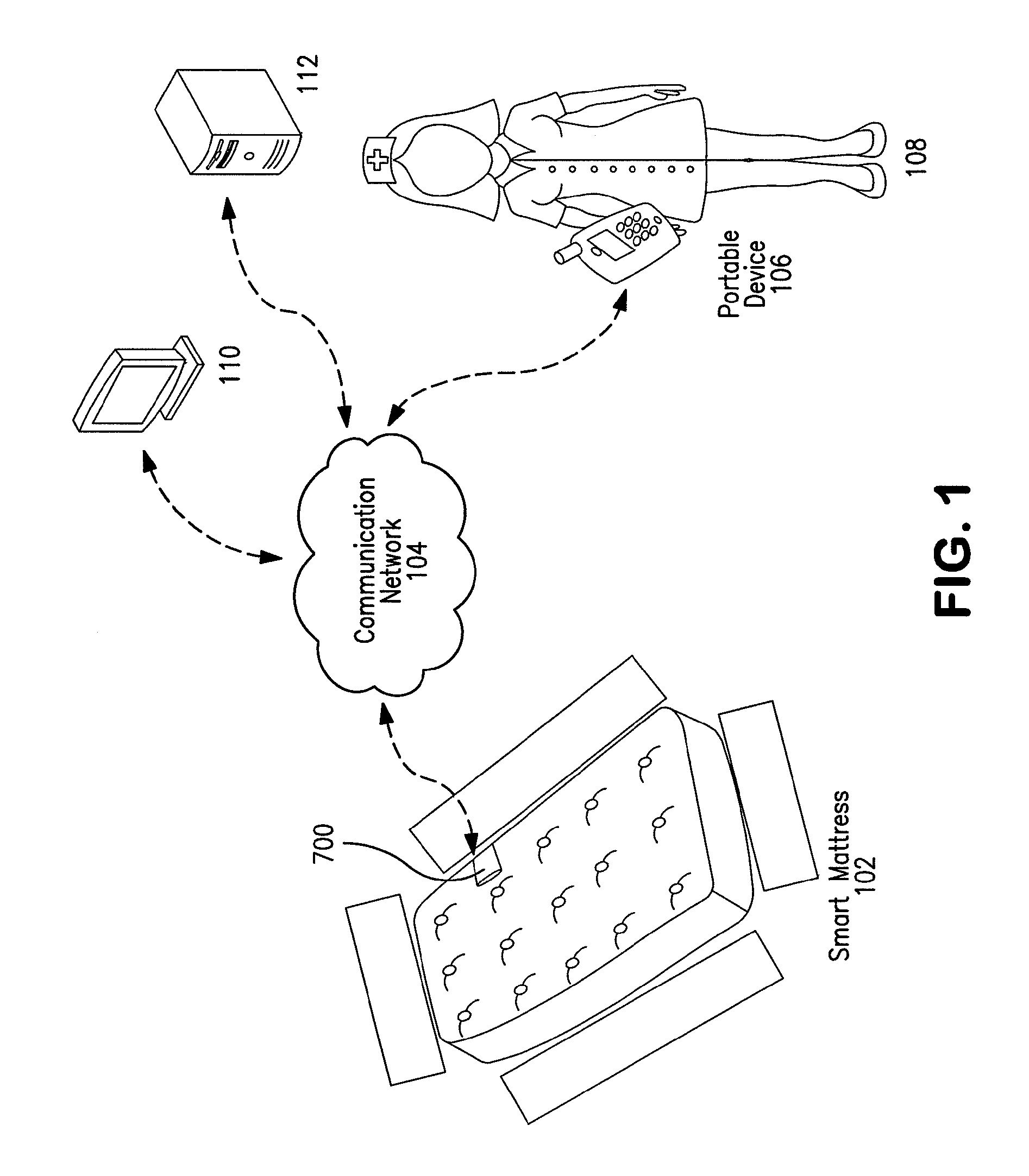
Smart mattress

a mattress and mattress technology, applied in the field of smart mattresses, can solve the problems of requiring an excessive number of cables, affecting the monitoring of patients, and the access of such patients, so as to monitoring, improve the efficiency of monitoring, and save costs

Inactive Publication Date: 2014-03-18
EVACUSLED
View PDF55 Cites 67 Cited by
  • Summary
  • Abstract
  • Description
  • Claims
  • Application Information

AI Technical Summary

Benefits of technology

[0012]Health care providers are very mobile, and the adoption of enhanced wireless technology by health care organizations, especially when harnessed properly, can help to improve, even automate, patient care and monitoring, save costs, and reduce staff injuries. It is indisputable that computer networks are commonplace in health care organizations and in some places are indispensable. However, most of the computer devices and monitoring devices are connected through the use of wires; this usually means that their use is limited to a fixed place. A Smart Mattress eliminates many of the wires associated with current methods and allows for greater flexibility in patient monitoring.

Problems solved by technology

A major concern with current noninvasive medical instruments is that they are often bulky and require an excessive number of cables in order to report the measurements to a computer or physician.
Access to such patients is difficult during normal treatment, but becomes a real problem in emergency situations where rapid evacuation may be required.
In such emergencies, because of the issues mentioned above, most current medical instrumentation cannot be quickly and effectively packed up to preserve substantially uninterrupted patient monitoring.
This system, however, requires that a rigid pad be properly disposed and positioned beneath the mattress while physically connected to an auxiliary device, restricting both the mobility and versatility of the monitoring system.
As in Yesha, this is not a self-contained monitoring mattress and still requires auxiliary equipment to receive and process sensor data.
As in Yesha, the system is not self-contained and also does not permit storage of patient data.
One apparent disadvantage is the lack of a self-contained system and the reliance on or requirement of an auxiliary device.
Another disadvantage is the lack of embedded storage for patient identification and other data, such as a patient's chart information.
However, most of the computer devices and monitoring devices are connected through the use of wires; this usually means that their use is limited to a fixed place.

Method used


Image

  • Smart mattress
  • Smart mattress
  • Smart mattress

Examples


Embodiment Construction

[0029]A preferred embodiment of the present invention will be described herein below with reference to the accompanying drawings. In the following description, well-known functions or constructions are not described in detail since they would obscure the invention in unnecessary detail.

[0030]For this application the following terms and definitions shall apply:

[0031]The terms “communicate” and “communicating” as used herein include both conveying data from a source to a destination and delivering data to a communications medium, system, channel, network, device, wire, cable, fiber, circuit and / or link to be conveyed to a destination, and the term “communication” as used herein means data so conveyed or delivered. The term “communications” as used herein includes one or more of a communications medium, system, channel, network, device, wire, cable, fiber, circuit and link.

[0032]The term “processor” as used herein means non-transitory processing devices, apparatus, circuits, components...


PUM

PropertyMeasurementUnit
timeaaaaaaaaaa
leakage currentaaaaaaaaaa
thickaaaaaaaaaa

Abstract

A mattress has a sensor pad affixed on a top surface thereof. The sensor pad has (i) a matrix array of plural pressure sensors, (ii) plural row conductors, and (iii) plural column conductors. Each intersecting row and column conductor provides an electrical signal from a corresponding sensor when pressure is applied thereto. The sensor pad has plural through-holes therein disposed between the plural row conductors the plural column conductors, respectively. Preferably, at least one patient-mounted physiological sensor is configured to provide an output signal corresponding to a patient physiological parameter. An electronic unit is mounted inside the mattress and is configured to receive signals from the sensor pad. The electronic unit has a data storage unit preferably storing (i) patient identification information, (ii) patient physiological information, and (iii) mattress information. A wireless transmitter is coupled to the electronic unit and is configured to wirelessly communicate at least the stored patient physiological information to an off-mattress device.

Description

[0001]This application is a Continuation-In-Part of U.S. patent application Ser. No. 12 / 862,253, filed Aug. 24, 2010, the entire contents of which are incorporated herein by reference.[0002]Reference is hereby made to the computer program listing appendix submitted herewith. The material in the appendix is hereby incorporation-by-reference in the specification. One appendix is submitted herewith and includes files: Acquisition Thread; PadGenerator; Patient; Program; SMatrix; AvgGraph Designer; AvgGraph; BasePane Designer; BasePane; BodyMap Designer; BodyMap; LogCntrl Designer; LogCntrl; Pane Caption Designer; PaneCaption; Patient Ctrl Designer; PatientCtrl; DesignGridForm Designer; DesignGridForm; FormMain Designer; FormMain; PatientForm Designer; PatientForm; FileList; AssemblyInfo; Resources.Designer; and Settings.DesignerTECHNICAL FIELD[0003]The present invention relates to a Smart Mattress for the real-time medical monitoring of individuals such as hospital patients, bed-ridden ...

Claims


Application Information

Patent Timeline
Patent Type & Authority Patents(United States)
IPC IPC(8): G01L15/00A61B5/00A61B5/0205A61B6/04G01L19/00A47C27/00
CPCA61B6/0407G01L15/00A61B5/6892A61B5/0002A61B2562/0247G01L19/0092A61B2505/00G01L2019/0053A47C27/002A61B2562/046A61B5/0205A61B2560/0468A61B5/0015A47D15/001
Inventor KENALTY, CHRISTOPHERGORDON, MIRIAMKATZ, HART VICTOR
Owner EVACUSLED
Why Eureka
Try Eureka