Fixing device, carrying device and image forming apparatus

a technology of fixing device and carrying device, which is applied in the direction of electrographic process apparatus, thin material handling, instruments, etc., can solve the problems of insufficient fixation of developer in both side end portions of the sheet, excessive stress given to the belt, and disordered image, so as to reduce the deformation of curves and the like, the effect of variable pressurizing force applied to the sh

Active Publication Date: 2009-01-01
KONICA MINOLTA BUSINESS TECH INC
View PDF4 Cites 22 Cited by
  • Summary
  • Abstract
  • Description
  • Claims
  • Application Information

AI Technical Summary

Benefits of technology

[0060]According to the image forming apparatus of the present invention, by employing the fixing device, the occurrence of insufficient fixation at the end portion of the sheet is reduced even when the thickness of the toner particle layer is thick, and a variation in the pressurizing force applied to the sheet is reduced in the lengthwise direction of the roller. Therefore, an image that is entirely uniform and clear can be obtained. Moreover, deformations of curves and the like are reduced at the end portions of the sheet.

Problems solved by technology

However, when a belt of a laminate structure including a metal layer is used in the belt-type fixing device that has the hard pressure roller and the soft fixing roller as described above, it is concerned that an excessive stress is given to the belt depending on the contact condition of the hard pressure roller and the soft fixing roller.
As a result, fixation of the developer is insufficient in both side end portions of the sheet, or a disorder of the image occurs as a consequence of the outward movement of the unfixed developer toward the end portions.
Since developers of a plurality of colors are layered on the sheet particularly in a full-color image forming apparatus, the disorder of the image often occurs.
Moreover, when the fixing belt includes a metal layer (electromagnetic induction heating layer), an excessive bending stress is generated in the metal layer, possibly causing cracks.

Method used


Image

  • Fixing device, carrying device and image forming apparatus
  • Fixing device, carrying device and image forming apparatus
  • Fixing device, carrying device and image forming apparatus

Examples


first embodiment

THE FIRST EMBODIMENT

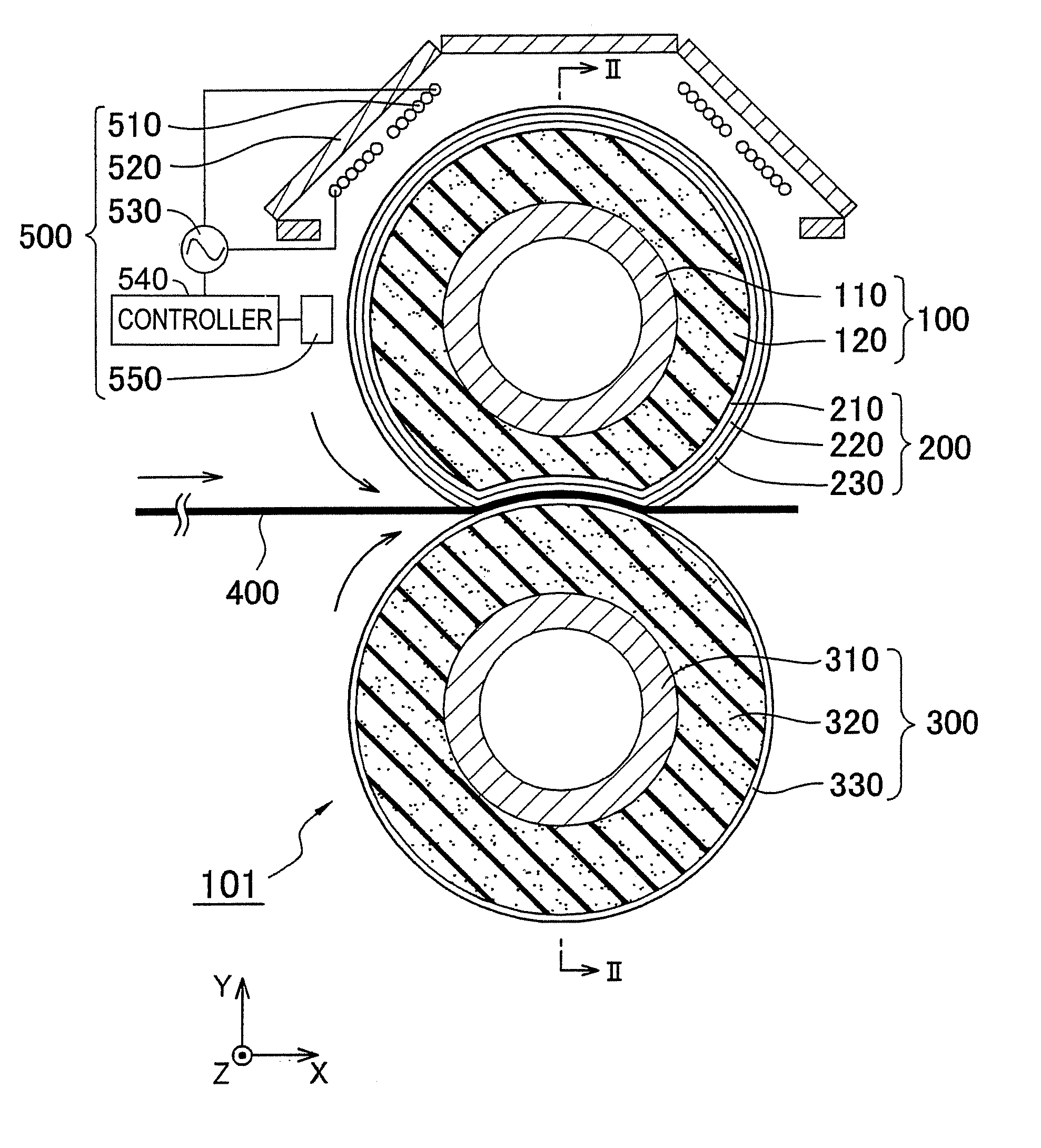
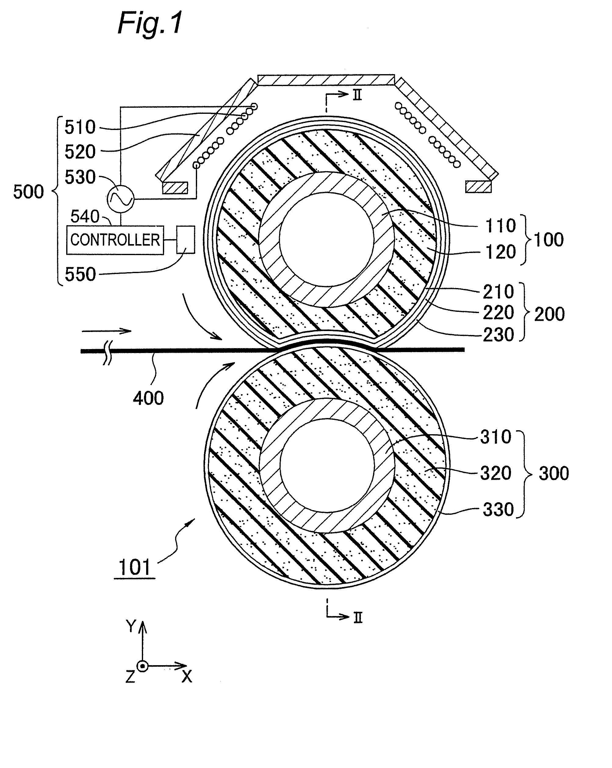
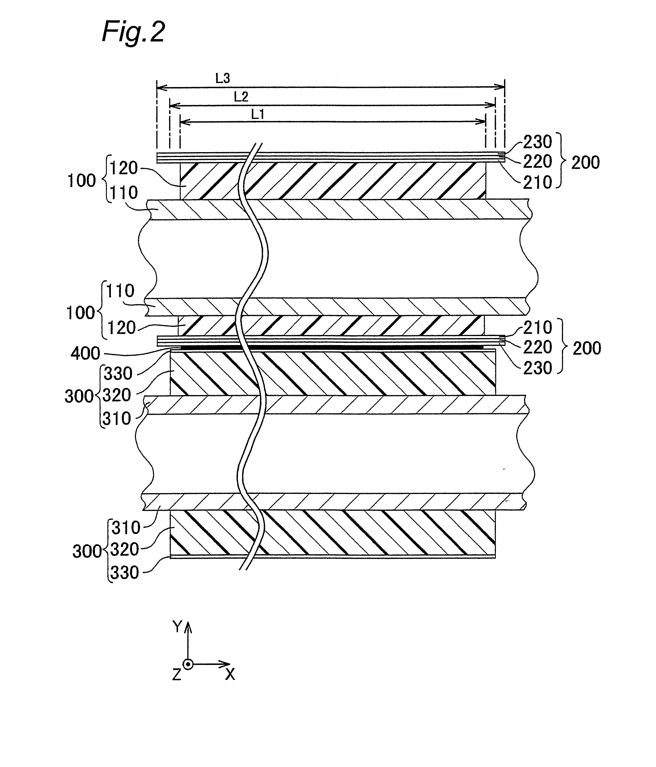
[0082]FIG. 1 is a side view of the fixing device of an electrophotographic image forming apparatus (e.g., copying machine, printer, facsimile, complex machine) according to the first embodiment of the present invention, the apparatus being entirely denoted by the reference numeral 101. FIG. 2 is a sectional view of the fixing device viewed from the direction II-II of FIG. 1. The cross section in FIG. 2 contains in its plane the central axes of two rollers 100, 300 (not shown) described later.

[0083]Referring to the figure, the fixing device 101 has a heating roller 100 as a first roller, and a pressure roller 300 as a second roller placed parallel to the heating roller 100. The heating roller 100 is externally provided with a cylindrical fixing belt 200 that has an inside diameter exactly identical or approximately identical to the outside diameter of the heating roller 100 or slightly larger than the outside diameter of the heating roller 100, and the heating rol...

second embodiment

THE SECOND EMBODIMENT

[0118]FIG. 6 is a sectional view of a fixing device 901 according to the second embodiment of the present invention. The cross section of FIG. 6 contains in its plane the central axes (not shown) of two rollers 900, 300 described later. In the fixing device 901, the fixing roller 900 includes a core metal 910 and an elastic layer 920 that has a heat-insulating property and covers the outer peripheral surface of the core metal 910 as in the fixing roller 100 described in the first embodiment. The material used for the core metal 910 is the same as that of the core metal 110, and the material and hardness of the elastic layer 920 are the same as those of the elastic layer 120.

[0119]The elastic layer 920 has an annular recess portion 925 continuous in the circumferential direction of the outer peripheral portion in both end regions E other than a region A through which the sheet passes in the lengthwise direction X of the fixing roller 900 shown in FIG. 6. In this ...

third embodiment

THE THIRD EMBODIMENT

[0124]Although the cross section of the recess portion 925 has the rectangular shape in FIG. 6, it is not limited to the shape. There may be a recess portion 926 that has a triangular cross section shown in FIG. 7A, a recess portion 927 that has a laterally U-shaped cross section shown in FIG. 7B, a recess portion 928 that has a trapezoidal cross section shown in FIG. 7C or a recess portion 929 that has a bird's beak-shaped cross section shown in FIG. 7D. It is noted that each of these recess portions 926, 927, 928, 929 has a form of an annular one-sided groove continuous in the circumferential direction as in the recess portion 925 shown in FIG. 6.

[0125]The recess portion 926 having the triangular cross section shown in FIG. 7A has an inclined portion of which the outside diameter dimension is linearly reduced outwardly in the lengthwise direction X. In this example, the inclined portion is inclined at an angle of not smaller than 20° or at an angle of 30° in th...


PUM


Abstract

The conveying device of the present invention comprises a cylindrical first roller, a cylindrical second roller that has a surface hardness higher than a surface hardness of the first roller, and a belt placed in a state surrounding either the first roller or the second roller. The conveying device moves an object to be conveyed by bringing the first roller and the second roller in pressure contact with each other via the belt and making the object pass through a nip portion formed of the belt and the first roller or the second roller facing the belt. A length in a lengthwise direction of an outer peripheral portion of the first roller is shorter than a length in a lengthwise direction of an outer peripheral portion of the second roller.

Description

[0001]This Nonprovisional application claims priority under 35 U.S.C. §119(a) on Patent Applications No. 2006-276389 and No. 2007-262264 filed in Japan on Oct. 10, 2006 and Oct. 5, 2006, respectively, the entire contents of which are hereby incorporated by reference.BACKGROUND OF THE INVENTION[0002]The present invention relates to image forming apparatuses such as printers, copying machines, facsimiles or complex machines that have the functions of them in a complex form and to fixing devices and conveying devices for use in the image forming apparatuses.[0003]In an electrophotographic image forming apparatus, a developer carried on a sheet that is an image carrier is fixed to the sheet by applying heat and a pressure to it. For the above purpose, a roller made of a solid rubber or the like has conventionally been used as heating means for heating the sheet and the developer in a fixing device incorporated in the image forming apparatus. However, a belt-type fixing device employing ...

Claims


Application Information

Patent Timeline
Patent Type & Authority Applications(United States)
IPC IPC(8): G03G15/20B65H5/02
CPCG03G15/2053G03G15/2028G03G2215/2025
Inventor SHIMIZU, YOSUKEURANO, ETSUAKIMURAKAMI, MASANORIINOUE, KEISUKEMASUDA, TOMOHIKO
Owner KONICA MINOLTA BUSINESS TECH INC
Why Eureka
Try Eureka