Power supply apparatus for sliding door

a technology for power supply apparatus and sliding door, which is applied in the direction of electric/fluid circuit, electric devices, transportation and packaging, etc., can solve the problems of cable guide damage, poor appearance, and risk of treading, so as to prevent the wiring body from being damaged, good appearance, and good appearance

Active Publication Date: 2009-01-08
FURUKAWA ELECTRIC CO LTD
View PDF39 Cites 6 Cited by
  • Summary
  • Abstract
  • Description
  • Claims
  • Application Information

AI Technical Summary

Benefits of technology

[0030]According to the present invention, it is possible to provide a power supply apparatus for sliding door in which a wiring body for supplying power to sliding door is arranged to run in such a manner that the wiring body is not exposed outside. Since the power supply apparatus for sliding door of the present invention has a configuration in which the wiring body moves inside the guide rail accompanied with the opening and closing of the sliding door, it is possible to prevent the wiring body from being exposed outside and being damaged or from presenting a poor appearance.
[0031]In the power supply apparatus for sliding door of the present invention, since the wiring body is arranged to run on the back surface of the bracket, it is possible to prevent the wiring body from being exposed outside accompanied with the opening and closing of the sliding door and to provide the power supply apparatus which achieves a good appearance. Furthermore, since the power supply apparatus for sliding door of the present invention has such a configuration that the exterior tube for receiving the wiring body moves inside the guide rail receiving portion accompanied with the opening and closing of the sliding door, it is possible to prevent the wiring body from being exposed outside and being damaged or from presenting a poor appearance.
[0032]According to the present invention, it is possible to provide a power supply apparatus for sliding door for preventing the wiring body from randomly moving between the vehicle body and the sliding door. According to the power supply apparatus of the present invention, since the wiring body is arranged to run along the edge portion of the bracket, it is possible to prevent the wiring body from randomly moving between the vehicle body and the sliding door accompanied with the opening and closing of the sliding door and to provide the power supply apparatus for sliding door which achieves a good appearance.
[0033]According to the present invention, it is possible to provide a power supply apparatus for sliding door in which the exterior tube suitable for the behavior of the wiring body accompanied with the opening and closing of the sliding door, is provided. In the power supply apparatus for sliding door of the present invention, since the exterior tube is provided at least in the running position of the bracket where the wiring body is mostly damaged, it is possible to prevent the wiring body from being damaged

Problems solved by technology

However, the conventional power supply apparatus for sliding door cause a problem that it presents a poor appearance since the wiring body become visible and invisible from passenger and randomly moves in the opening and closing of the sliding door.
Furthermore, if the wiring body is randomly exposed when getting in and getting out of the vehicle with the sliding door fully opens, there is a risk to tread on it.
And, in the conventional power supply apparatus in which the wiring body is received in the cable guide, there is a risk to tread on and cause damage to the cable guide.
Furthermore, an exterior tube such as guide tube or corrugated tube is used for controlling the movement of the wiring body, however, since the wiring body is arranged to run only after the whole wiring body from vehicle body to sliding door is received in one exterior tube, it cause a problem that time and labor are required for installation of the exterior tube or for running of the wiring body.
Furthermore, since both one portion of the wiring body which moves and the other portion which does not move in the opening and closing of the sliding, are received in one unit of the exterior tube, it cause a problem that considerable stress is applied on the wiring body as it moves or protection performance tan not be sufficiently obtained.

Method used


Image

  • Power supply apparatus for sliding door
  • Power supply apparatus for sliding door
  • Power supply apparatus for sliding door

Examples


first embodiment

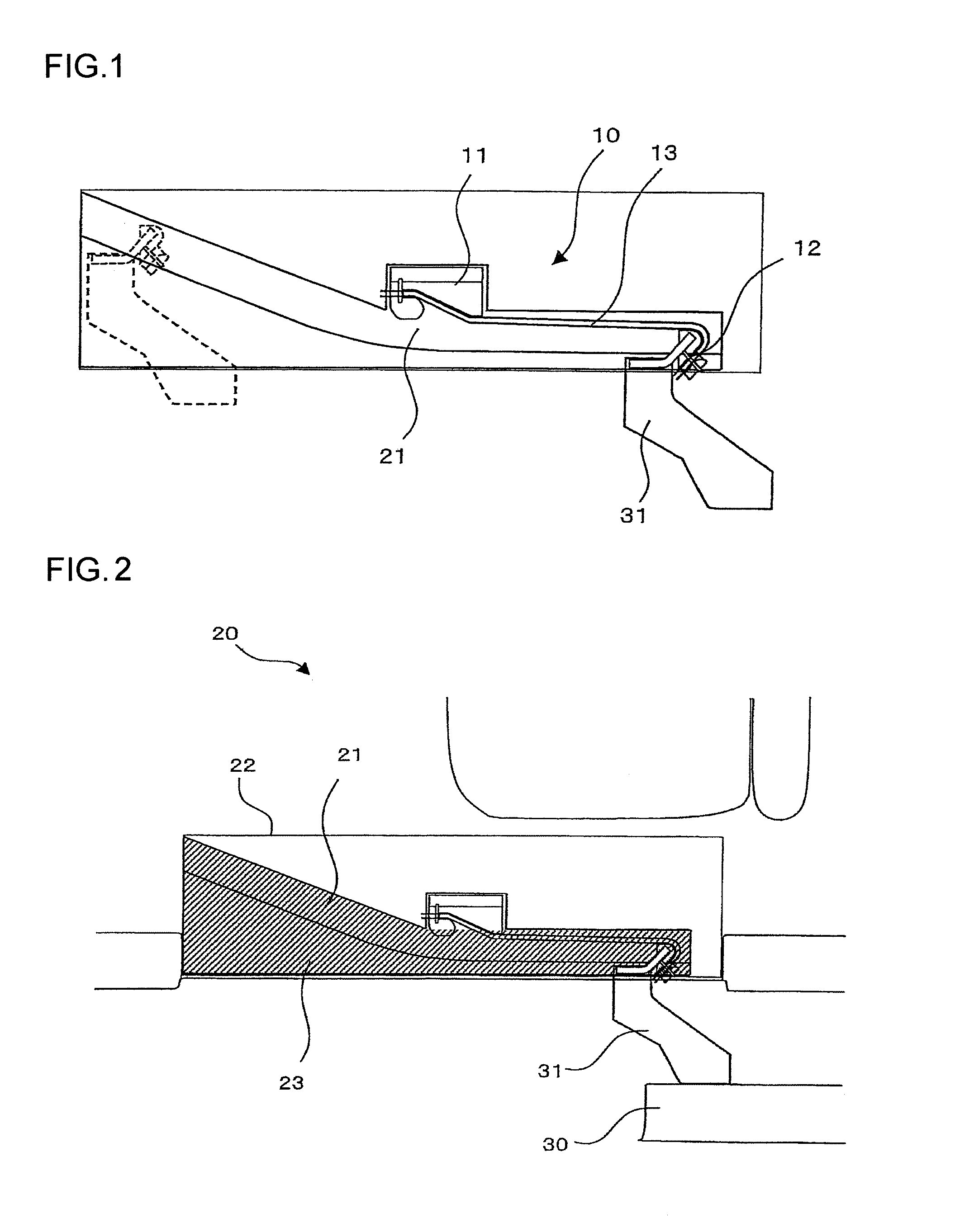
[0128]Referring to the FIG. 1, there is illustrated a plan view of the power supply apparatus for sliding door according to the present invention. The power supply apparatus for sliding door 10 according to the present invention is provided in the vicinity of the guide rail 21 provided in the vehicle body for opening and closing the sliding door. FIG. 2 shows one embodiment of the vehicle configuration in the vicinity of the sliding door. In the FIG. 2, the sliding door 30 is supported with the bracket 31 provided on the lower front portion of the sliding door 30, another bracket provided on the upper front portion of the sliding door 30 and another bracket provided on the rear portion of the sliding door 30, which are not shown in the figures.

[0129]On the vehicle body 20 side, the step 22 is provided in a sliding door entry portion and the guide rail 21 is provided underneath the step 22. The guide rail receiving portion 23 (shown in FIG. 2 as shaded) in which the guide rail 21 is ...

second embodiment

[0147]The power supply apparatus for sliding door according to the present invention is explained with reference to FIG. 7. In the power supply apparatus for sliding door 40 shown in FIG. 7, the aspect of body side fixing member 41 is opposite to the one of the embodiment shown in FIG. 1. In this case, the wiring body is in contact with the oblique surface 41a when the sliding door 30 is fully closed, and is wound around the first R part 41b when the sliding door is fully opened. In this embodiment, the wiring body 13 is also able to move inside the guide rail receiving portion 23 without a risk that the wiring body 13 is exposed outside even when the sliding door 30 is located in the full-closing position, in the full-opening position and in the position between the full-opening position and full-closing position.

third embodiment

[0148]The plan view of the power supply apparatus for sliding door according to the present invention is shown in FIG. 8. The power supply apparatus for sliding door 100 of the present embodiment is provided in the vicinity of the guide rail 141 provided in the vehicle body for opening and closing the sliding door. One embodiment of the vehicle configuration in the vicinity of the sliding door is as explained with reference to FIG. 2.

[0149]The power supply apparatus for sliding door 100 of the present invention includes, a vehicle body side fixing member 110 provided in the guide rail receive member 143, a bracket side fixing member 120 provided in the bracket 151, a wiring body 130 for supplying power from the vehicle body 140 side to the sliding door 150 side, a running member for bracket 160 for running the wiring body 130 on the back surface of the bracket and holding the wiring body 130.

[0150]The condition in which the running member for bracket 160 is fixed on the back surface...


PUM


Abstract

The power supply apparatus for sliding door 100 includes the vehicle body side fixing member 110 provided in the guide rail receiving portion 143, the bracket side fixing member 120 provided in the bracket 151, the wiring body 130 for supplying power from the vehicle body 140 side to the sliding door 150 side and the running member for bracket 160 for running and holding the wiring body 130 on the back surface of the bracket 151. The wiring body 130 is held with the vehicle body side fixing member 110 and the bracket side fixing member 120, and is arranged to run on the back surface of the bracket 151 with the running member for bracket 160.

Description

TECHNICAL FIELD[0001]This invention relates to the power supply apparatus for sliding door for supplying power all the time from the body side of the automobile to devices within the sliding door.BACKGROUND ART[0002]Such devices as the power window motors, switches, speakers or the like are incorporated into the sliding door used for a van or a wagon car or the like. In order to supply power from the vehicle body side to the devices, it must be designed that wiring body (wire harness) is arranged to run from the vehicle body side to the sliding door side, while the wire harness smoothly follow the opening and closing of the sliding door. A round wire having high flexibility has been conventionally used as the wire harness.[0003]It is known that there is proposed the power supply apparatus for sliding door in which the wire harness winding unit is provided in the vehicle body side, and the surplus length of the wire harness accompanied with the opening and closing of the sliding door...

Claims


Application Information

Patent Timeline
Patent Type & Authority Applications(United States)
IPC IPC(8): B60L1/00
CPCB60R16/0207
Inventor USHIYAMA, MASATOSHIENOMOTO, NORITSUGUMUKAI, YASUHIKOMIYAJIMA, KAZUO
Owner FURUKAWA ELECTRIC CO LTD
Why Eureka
Try Eureka