Utility interactive inverter with var dispatch capabilities

a technology of inverter and dispatch capability, applied in the field of electric power distribution system, can solve the problems of increasing the cost of power generation on line, bringing resources online to supply additional power, and purchasing power from another source,

Active Publication Date: 2009-01-22
GRIDPOINT
View PDF4 Cites 46 Cited by
  • Summary
  • Abstract
  • Description
  • Claims
  • Application Information

AI Technical Summary

Benefits of technology

The patent text describes a closed loop control circuitry that is used in a specific embodiment. The technical effect of this circuitry is to provide precise and efficient control over a specific process or system. This can improve the overall performance and reliability of the system, and can also reduce the likelihood of errors or failures.

Problems solved by technology

The technical problem addressed in this patent text is the need for a more efficient and cost-effective way to manage the demand on electric power grids, as well as the need for a more centrally controlled and automated way of monitoring and reacting to voltage instability or generation shortfall.

Method used


Image

  • Utility interactive inverter with var dispatch capabilities
  • Utility interactive inverter with var dispatch capabilities
  • Utility interactive inverter with var dispatch capabilities

Examples


Embodiment Construction

[0020]Reference will now be made in detail to the preferred embodiments of the present invention, examples of which are illustrated in the accompanying drawings.

[0021]The present invention is described below with operational illustrations of devices and systems for dispatching reactive power to a power grid. It is understood that illustrations may be implemented by means of analog or digital hardware and computer program instructions. These computer program instructions may be provided to a processor of a general purpose computer, special purpose computer, ASIC, or other programmable data processing apparatus, such that the instructions, which execute via the processor of the computer or other programmable data processing apparatus, implements the functions or acts specified in the illustrations.

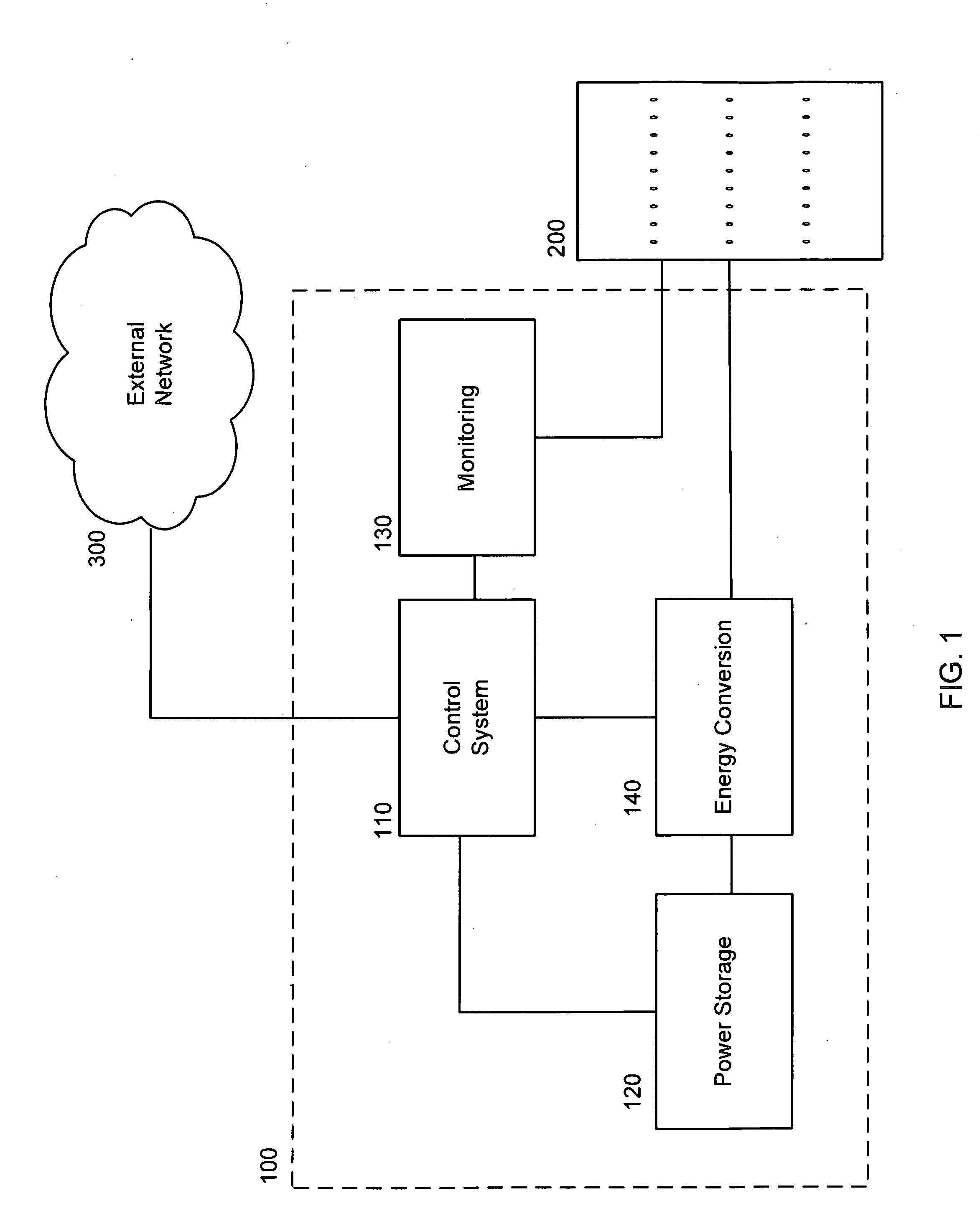
[0022]FIG. 1. illustrates an embodiment of a VAR dispatch device, 100. The device is connected to a power grid, 200, which may be, for example, the power grid of a local utility. The VAR dis...


PUM


Abstract

A VAR dispatch system. A central control system connected to a network is configured to receive data reflecting local variations in conditions on a power grid and to transmit system control commands over the network. A plurality of VAR dispatch devices are connected to the network and to the power grid. Each VAR dispatch device is configured to detect local variations in conditions on the power grid and to transmit the data reflecting such local variations to the central control system and to receive control commands from the central control system. Each VAR dispatch device is configured to store power and to output stored power to the power grid based on local variations in conditions on the power grid. Each VAR dispatch device is further configured to output stored power to the power grid when the VAR dispatch device receives system control commands from the central control system.

Description


Claims


Application Information

Patent Timeline
Owner GRIDPOINT
Why Eureka
Try Eureka