
Web separator with reverse rotation mechanism for tissue paper winding machine

Active Publication Date: 2009-01-29
CHAN LI MACHINERY
View PDF15 Cites 25 Cited by
  • Summary
  • Abstract
  • Description
  • Claims
  • Application Information

AI Technical Summary

Benefits of technology

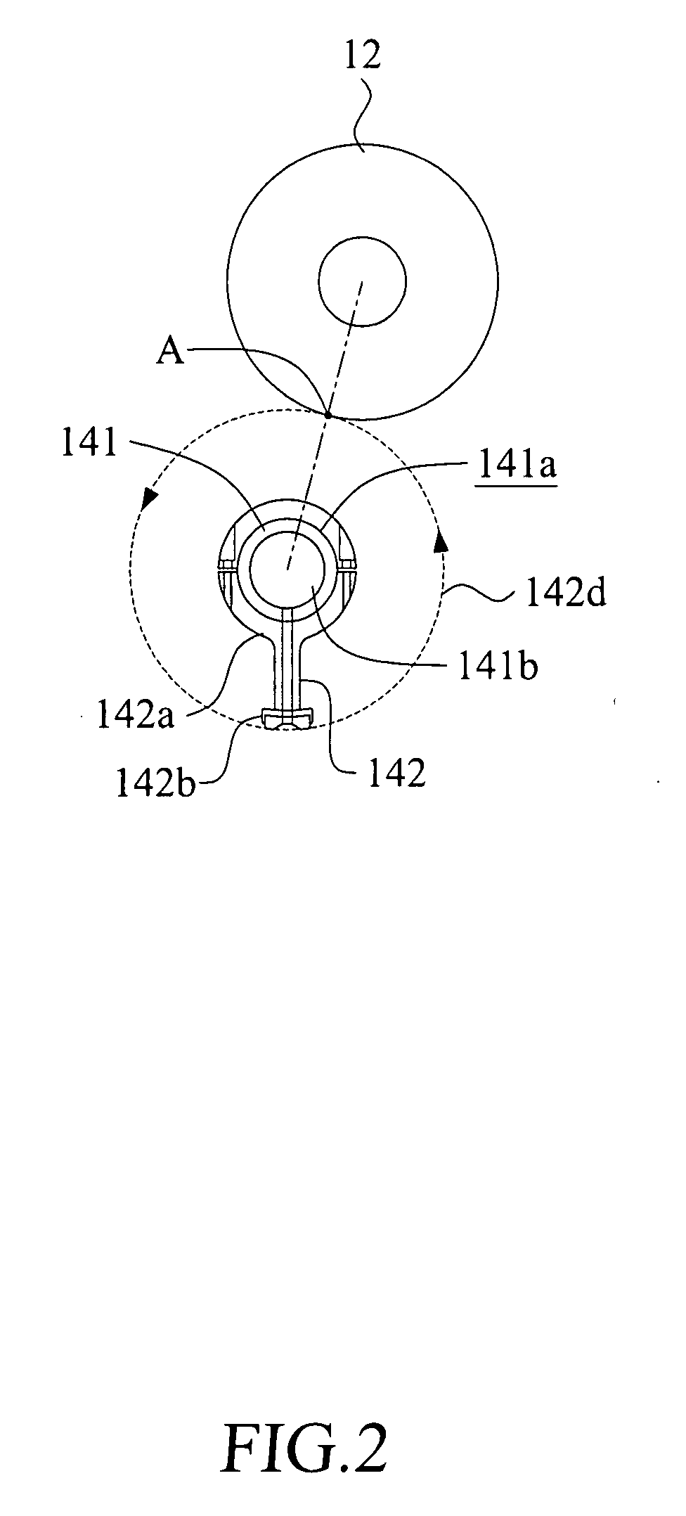
[0007]A primary object of the present invention is to provide a tissue paper winding machine including a web separator which is driven to rotate in a direction reverse to the feeding direction of the tissue paper that hinders the forward movement of the tissue paper and generates a pulling force at the tissue paper which is then pulled apart.
[0008]Another object of the present invention is to provide a web separator which includes a plurality of pinch arms connecting to a suction channel and a suction pump for drawing out air from the suction channel and the passages in the pinch arms to generate a suction force, that enables smooth winding of the tissue paper around a next core.
[0012]With the web separator, the tissue paper on the winding machine may be easily pulled apart with the pinch arm being rotated at any rotation speed, even if the tissue paper is made of a highly tough material. Moreover, with the suction pump, the pinch arm may suck the newly formed leading edge of the pulled apart tissue paper to facilitate smooth winding of the leading edge to a next core.

Problems solved by technology

The interrupting means interrupts the web material and consequently, the web material is torn.
Moreover, since the rotary member is rotated in a direction the same as the moving direction of the tissue paper in the winding machine, the rotary member does not provide the function of catching a new leading edge of the torn tissue paper for winding the leading edge to a next core.

Method used


Image

  • Web separator with reverse rotation mechanism for tissue paper winding machine
  • Web separator with reverse rotation mechanism for tissue paper winding machine
  • Web separator with reverse rotation mechanism for tissue paper winding machine

Examples


Embodiment Construction

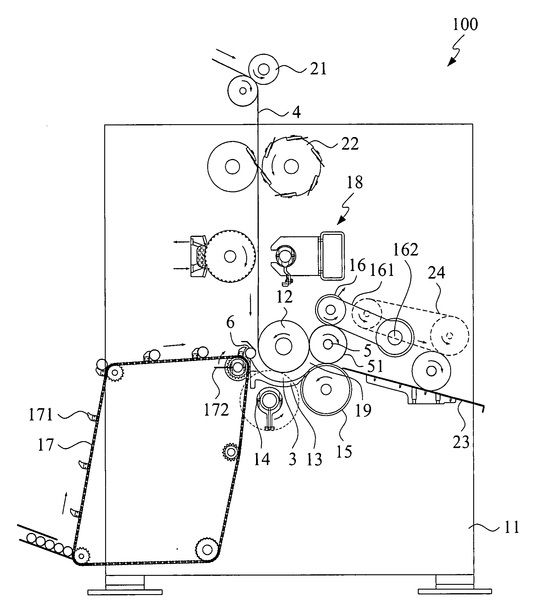
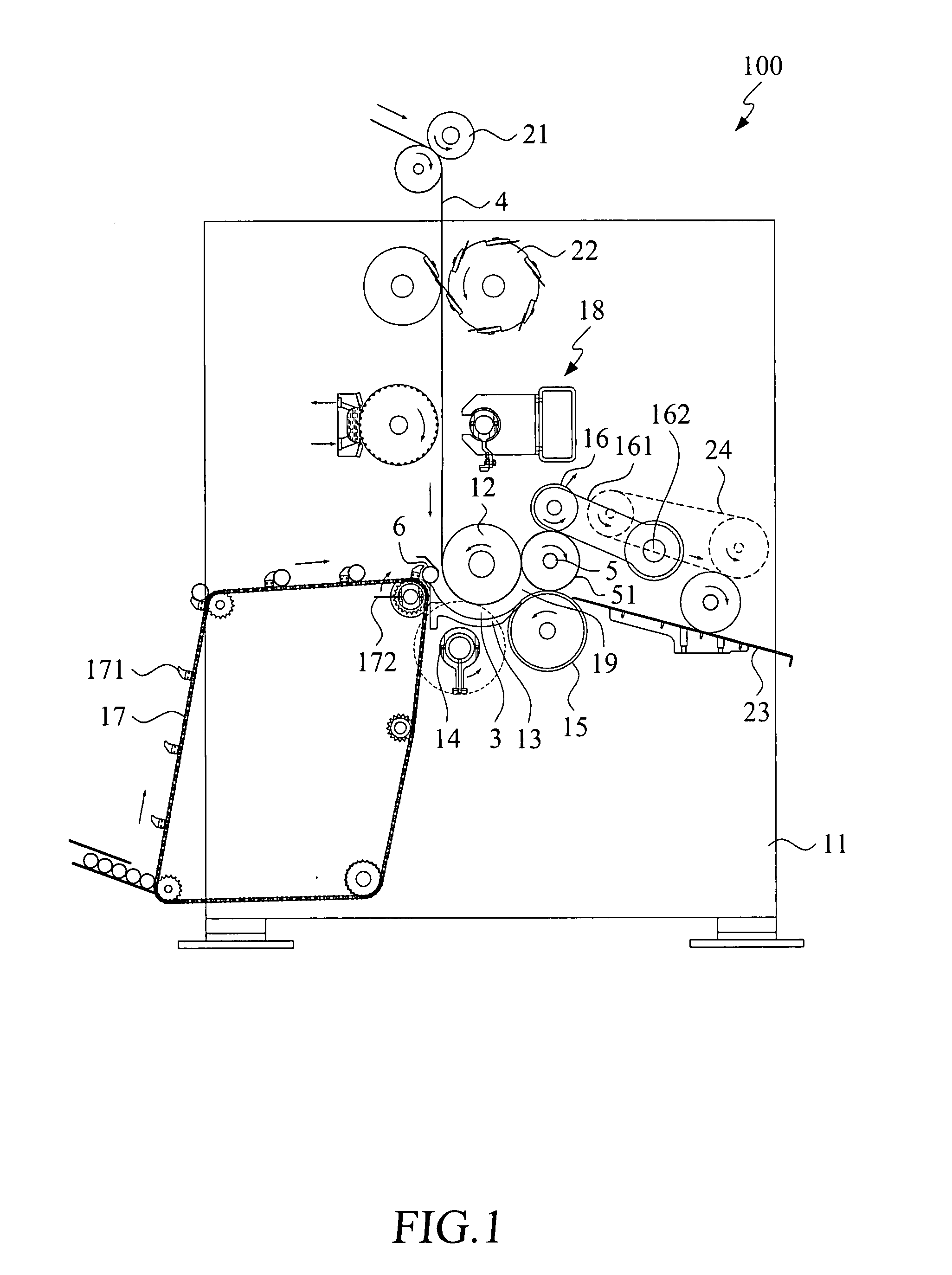
[0026]Please refer to FIG. 1, which is a side view of a tissue paper winding machine including a web separator with reverse rotation mechanism constructed according to a first embodiment of the present invention. The tissue paper winding machine is generally denoted a reference numeral 100, and includes a machine frame 11, a first winding roller 12, a plurality of core support plates 13 (only one can be seen in the figure), a web separator 14, a second winding roller 15, a rider roller 16, a conveyor 17, a gluing mechanism 18, a pair of feed rollers 21, a perforation roller 22, a chute 23, and a belt 24.

[0027]The core support plates 13 are located near and below the first winding roller 12, such that a channel 3 is defined between the core support plates 13 and the first winding roller 12. A winding nip 19 is defined between the first winding roller 12, the second winding roller 15, and the rider roller 16. A long tape of tissue paper 4 having a predetermined thickness and width is ...


PUM

PropertyMeasurementUnit
Areaaaaaaaaaaa
Frictionaaaaaaaaaa

Abstract

A tissue paper winding machine includes a first winding roller and a web separator arranged below the first winding roller. A tissue paper is fed into the winding machine to bear against a lower circumferential surface of the first winding roller and moves along a predetermined feeding direction for winding around a core. The web separator includes a pivot shaft, at least one pinch arm having a connecting end connected to the pivot shaft and a pressing end radially outward extended from the pivot shaft, and a driving mechanism for driving the pinch arm to turn about the pivot shaft reverse to the feeding direction of the tissue paper. When the pressing end of the pinch arm is turned to a separation position, it cooperates with the first winding roller to clamp the tissue paper therebetween, and applies a reverse pulling force to split the tissue paper.

Description

FIELD OF THE INVENTION[0001]The present invention relates to a web separator for a tissue paper winding machine, and more particularly, to a web separator which tears a web by a reverse rotation mechanism.BACKGROUND OF THE INVENTION[0002]In a conventional tissue paper winding machine, a core is generally sent by a conveyor to a first winding roller and pushed by a core inserter into a guiding passage to a winding nip, at where a long tape of tissue paper is wound around the core to form a roll of paper, such as a rolled tissue paper. When the winding of a first roll of paper is completed, the tissue paper is torn by a device.[0003]U.S. Pat. No. 5,769,352 discloses a web rewinding machine adaptable to different core diameters. The web winding machine includes an interrupting means which rotates about a rotating element at a speed slightly lower than the speed of the feed of the web material. The interrupting means interrupts the web material and consequently, the web material is torn...

Claims


Application Information

Patent Timeline
IPC IPC(8): B65H18/28
CPCB65H19/2269B65H19/267B65H2301/41425B65H2408/235B65H2301/41812B65H2406/33B65H2301/41426
Inventor TSAI, TUNG-I
Owner CHAN LI MACHINERY
Learn More