
Ink-jet recording apparatus, ink-jet copier and recording medium

a technology of inkjet copier and recording medium, which is applied in the direction of typewriters, printing, thin material processing, etc., can solve the problem of not having a decisive technology established, and achieve the effect of uniform image quality and high image quality printing

Inactive Publication Date: 2009-01-29
RICOH KK
View PDF34 Cites 13 Cited by
  • Summary
  • Abstract
  • Description
  • Claims
  • Application Information

AI Technical Summary

Benefits of technology

[0012]The present invention has been made in view of the situation described above, and a first object of the present invention is to achieve a good quality of images formed on both sides of a recording medium when double side printing is performed in an ink-jet recording apparatus so as to achieve saving resources.
[0013]A second object of the present invention is to make uniform image qualities on both sides when the double side printing is performed which achieves resource saving in the ink-jet recording apparatus.

Problems solved by technology

However, in such a technical field, the development is merely started now, and, thus, no decisive technology has been established yet.

Method used


Image

  • Ink-jet recording apparatus, ink-jet copier and recording medium
  • Ink-jet recording apparatus, ink-jet copier and recording medium
  • Ink-jet recording apparatus, ink-jet copier and recording medium

Examples


second embodiment

[0200]Next, the present invention will now be described using FIG. 7.

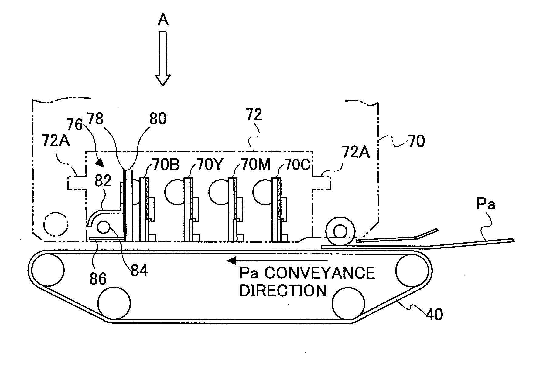
[0201]FIG. 7 shows the second embodiment in which a rear heating unit 90 is additionally provided so that the recording medium Pa can be heated also from the opposite side of the printed surface. The rear heating unit 90 also covers the wider range than the printing range of the recording medium Pa while the heating range extends along the multi-nozzle sequence / row arrangement direction, and thus, effective heating can be achieved. Furthermore, more effective ink heating and dryness are realizable by making the range heated into a larger range than the width of the recording medium Pa.

third embodiment

[0202]FIG. 8 shows the present invention in which such a rear heating unit 90 is made in contact with the conveyance belt 40, and thus is made to perform heating and dryness more effectively.

[0203]In this case, heating is made directly by means of the conveyance belt 40 which conveys the recording medium Pa. However, it is also possible to replace the conveyance belt 40 by another conveyance unit, for example, a drum structure (or a roller), and the recording medium Pa is directly heated by using the drum (roller) itself as a heating drum (roller). Thereby, still more effective heating and dryness is possible.

fourth embodiment

[0204]FIG. 9 illustrates the present invention. In this embodiment, printing is made in the order of C, M, Y and B (the ink of cyan, magenta, yellow and black), and, after that, a warm air applying unit 91 applies a heated air flow onto the printed surface of the paper sheet thus conveyed. Thus, a non-contact heating system is applied to evaporate the water in the ink, thus dry the ink, and, fix the same onto the paper sheet effectively.

[0205]FIGS. 10A and 10B illustrate the above-mentioned warm air applying unit 91 which is preferably applied in the embodiment of the present invention. FIGS. 9, 10A and 10B illustrate the warm air applying unit 91 in a diagrammatic sketch, and basically, it includes a ventilation device 91a, a heating device 91b, and a warm air application zone (warm air ventilation mouth) 91c.

[0206]A fan as shown, a pump, a compressor, or an accumulator combined therewith may be applied as the ventilation device 91a. As the heating device 91b, one utilizing a Joul...


PUM


Abstract

A containing member contains a recording medium which has a base member and granular material coated on both sides of the base member, and roughness of the surfaces of the coated granular material is smaller than the roughness of the base member. A printing unit includes an ink-jet recording head which jets recording liquid onto the recording medium. A conveyance unit and a conveyance path convey the recording medium, one side of which has been already printed, into the printing unit again in order to print image onto the other side thereof. A unit is provided for enabling the printing unit to print image on the recording medium such that the vertical orientations of the images printed both sides of the recording medium are coincide with each other.

Description

BACKGROUND OF THE INTENTION[0001]1. Field of the Invention[0002]The present invention relates to an ink-jet recording apparatus which performs recording on both sides of a recording medium, and ink-jet copier employing the ink-jet recording apparatus and a recording medium used therein.[0003]2. Description of the Related Art[0004]A non impact recording method has taken attention recently in terms of the fact that a noise occurring at a time of recording is so small that it can be almost ignored. In this situation, a so-called ink-jet recording method is very advantageous recording medium in that a high-speed recording can be achieved, and, also, a so-called ordinary paper can be applied without necessity of any special fixing processing. Accordingly, various methods have been put into practical use after being developed and improved, while some methods are still on development so as to be put into practical use in future in the same technical field.[0005]Such an ink-jet recording me...

Claims


Application Information

Patent Timeline
Patent Type & Authority Applications(United States)
IPC IPC(8): B41J2/01B41J3/60B41J13/00B41J21/00B65H15/00B65H85/00
CPCB41J3/60
Inventor SEKIYA, TAKURO
Owner RICOH KK
Learn More