Self-pumping hydropneumatic spring-damper unit

a hydropneumatic spring and self-pumping technology, applied in the direction of shock absorbers, mechanical equipment, transportation and packaging, etc., can solve the problem of high dependence on the amount of oil flowing through

Inactive Publication Date: 2009-02-05
ZF FRIEDRICHSHAFEN AG
View PDF7 Cites 23 Cited by
  • Summary
  • Abstract
  • Description
  • Claims
  • Application Information

AI Technical Summary

Problems solved by technology

With a constant cross section of this kind, the amount of oil that flows through is highly dependent upon pressure, which is undesirable in principle.

Method used


Image

  • Self-pumping hydropneumatic spring-damper unit
  • Self-pumping hydropneumatic spring-damper unit
  • Self-pumping hydropneumatic spring-damper unit

Examples


Embodiment Construction

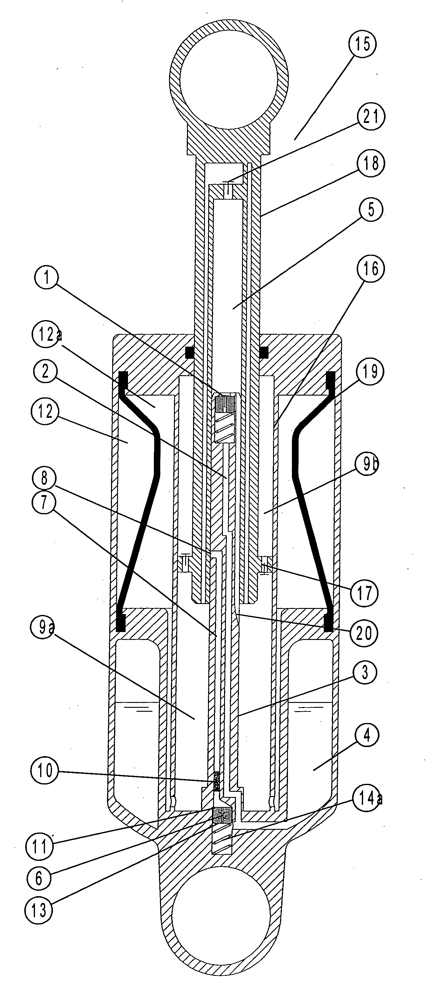
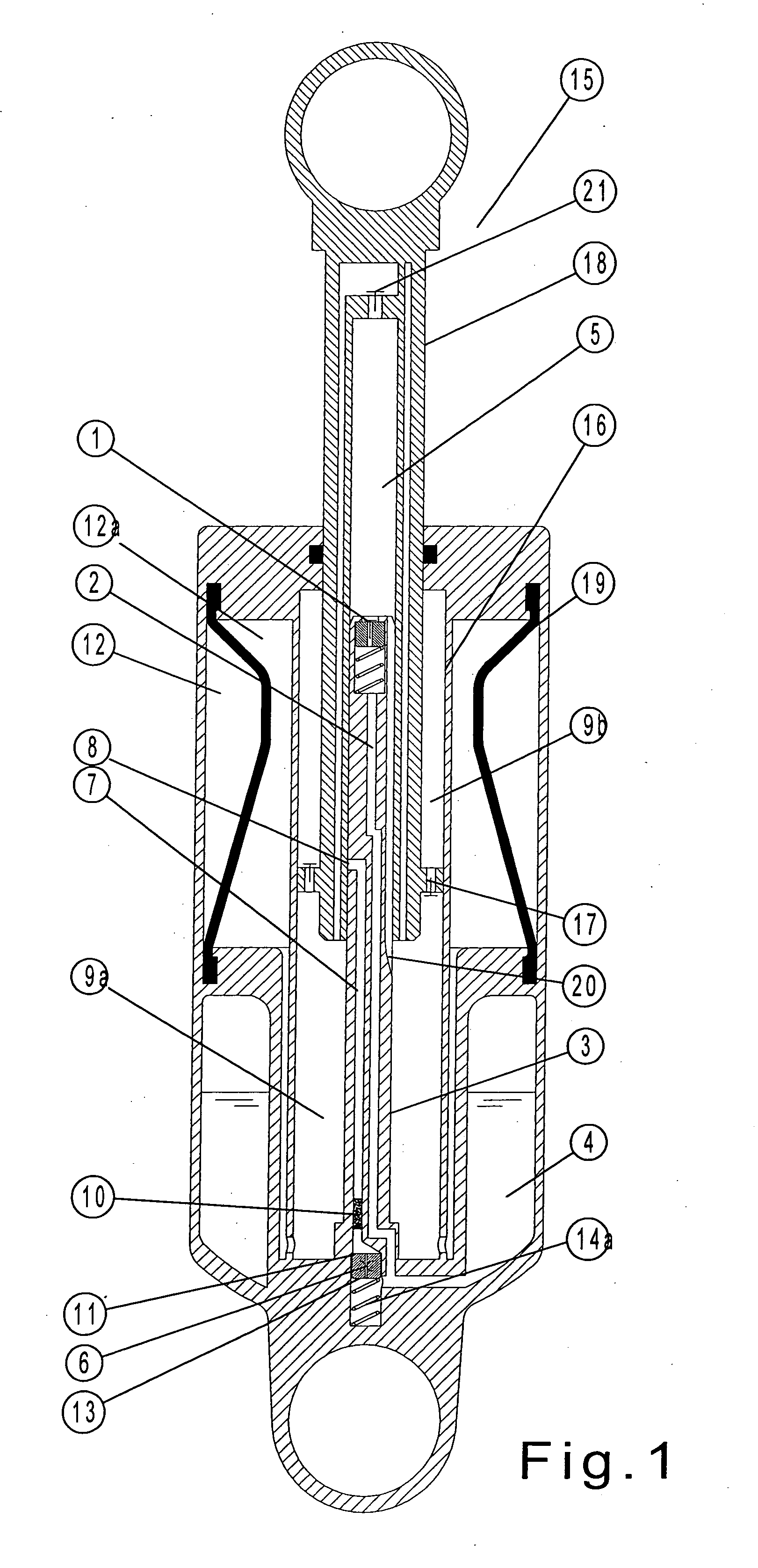
[0018]The self-pumping hydropneumatic spring-damper unit 15 for motor vehicles shown in FIG. 1 substantially comprises a work cylinder 16, in which a damping piston 17 slides. The damping piston 17 is formed at the end of a hollow piston rod 18. The work cylinder 16 is closed off on one side by an end wall and on the other side by the piston rod guide, through which the hollow piston rod 18 passes outward in a sealed manner. The spring-damper unit 15 is fastened by the end wall to the body of a vehicle (not shown) by a fastening eye, and at the other end of the spring-damper unit 15, the piston rod 18 is fastened to the axle of the vehicle by means of another fastening eye in a known manner. The work cylinder 16 is surrounded by an annular compensation chamber which is filled partly with oil and partly with gas. This compensation chamber is divided by an intermediate wall into a high-pressure gas cushion 12 and a low-pressure gas cushion 4. The high-pressure gas cushion 12 in the hi...


PUM


Abstract

A self-pumping hydropneumatic spring-damper unit with internal leveling control is provided. The spring-damper unit has an oil-filled work cylinder under pressure by gas cushions. A damping piston is displaceable in the work cylinder and arranged at the end of a hollow piston rod whose hollow space serves to receive a pump by means of a pump rod fastened to the work cylinder. Damping medium is sucked out of a reservoir space when the piston rod moves outward and is conveyed into the work space when the piston rod moves inward. The pump rod has a control opening and, at a distance therefrom, an outlet bore for pressure equilibrium between work spaces in the work cylinder. At least one pressure-dependent throttle point is provided in the pump space between the high-pressure and low-pressure gas cushions. A first flow connection in the pump rod provided with at least one check valve connects the low-pressure gas cushion to the pump space. A second flow connection having the throttle point is connected to the work space by the outlet bore.

Description

BACKGROUND OF THE INVENTION[0001]1. Field of the Invention[0002]The invention is directed to a self-pumping hydropneumatic spring-damper unit with internal leveling control.[0003]2. Description of the Related Art[0004]Self-pumping hydropneumatic spring-damper units with internal leveling control are already known (DE 10 2004 009 224 B3), wherein the damping piston is arranged in a work cylinder so as to be displaceable axially. This damping piston is under pressure by a high-pressure gas cushion and a low-pressure gas cushion. The damping piston is arranged at the end of a hollow piston rod, which has a hollow space designed as a pump space. A pump rod is located inside the pump space and fastened to the work cylinder projecting into the hollow piston rod. Oil is sucked out of the low-pressure chamber when the piston rod moves outward. Oil is conveyed into the work space when the piston rod moves inward. When the vehicle level height is exceeded or during spring rebound, an outlet b...

Claims


Application Information

Patent Timeline
Patent Type & Authority Applications(United States)
IPC IPC(8): F16F9/18
CPCB60G15/12B60G17/044F16F9/512B60G2202/242F16F9/092B60G2202/152
Inventor KIRCHNER, HOLGERSCHMITZ, KLAUSBECK, HUBERT
Owner ZF FRIEDRICHSHAFEN AG
Why Eureka
Try Eureka