
Cutting tool, tool body and cutting insert therefor

a cutting tool and tool body technology, applied in the field of cutting tools, can solve the problems of affecting the robustness of the tool, and the difficulty of the cutting tool to provide robust mechanical support,

Active Publication Date: 2009-02-05
ISCAR LTD
View PDF12 Cites 26 Cited by
  • Summary
  • Abstract
  • Description
  • Claims
  • Application Information

AI Technical Summary

Benefits of technology

[0010]According to an aspect of some embodiments of the invention, the forces generate a torque that presses an abutment surface of the insert against an abutment surface of the tool body thereby substantially fixing the orientation of the insert and its cutting edge relative to the tool body.

Problems solved by technology

However, providing a cutting tool with relatively large reach needed for shaping or grooving an internal surface may affect the robustness of the tool.
As a result, it may be difficult for the cutting tool to provide robust mechanical support for the cutting insert near the cutting tool's cutting edge.

Method used


Image

  • Cutting tool, tool body and cutting insert therefor
  • Cutting tool, tool body and cutting insert therefor
  • Cutting tool, tool body and cutting insert therefor

Examples


Embodiment Construction

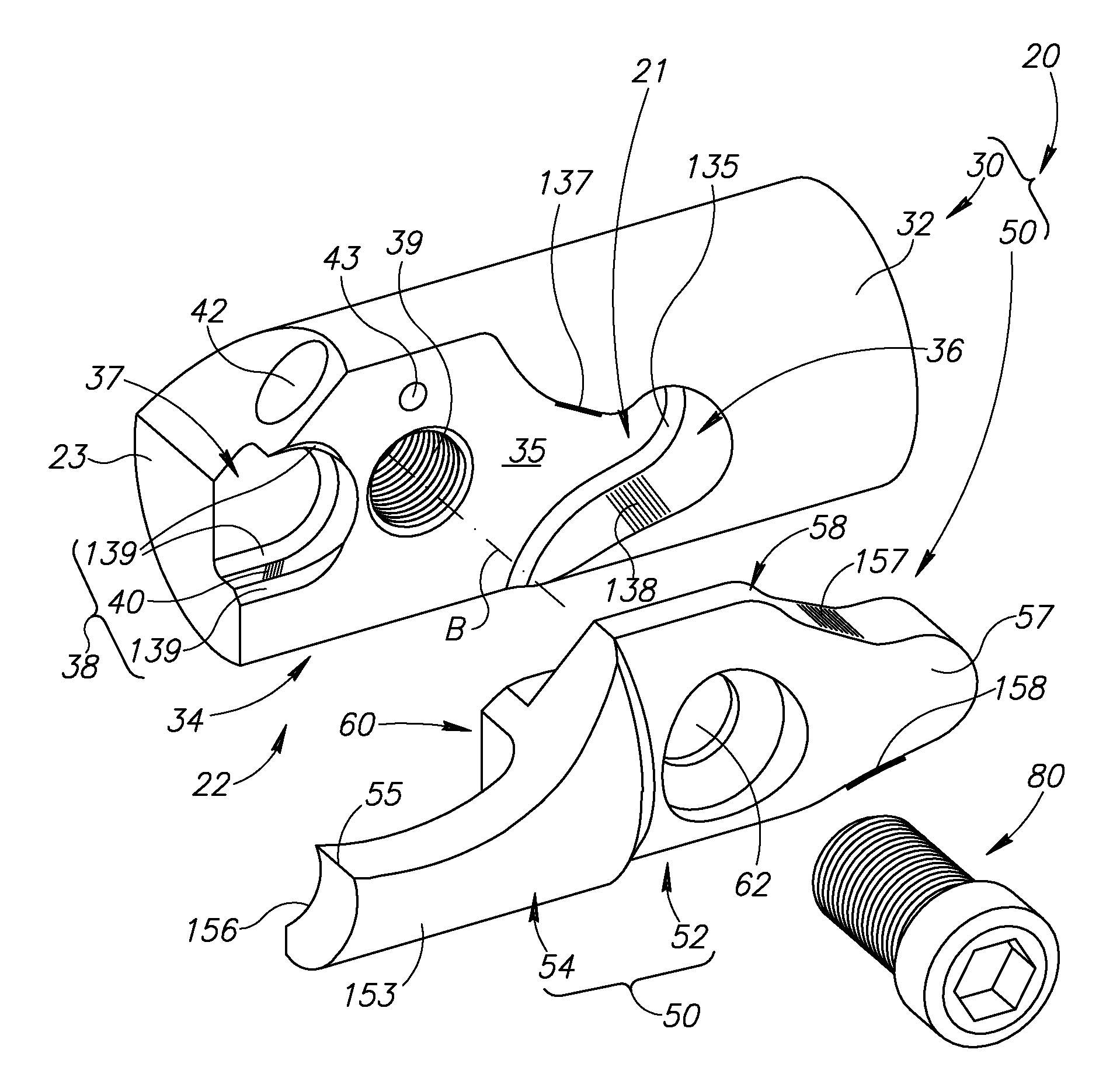
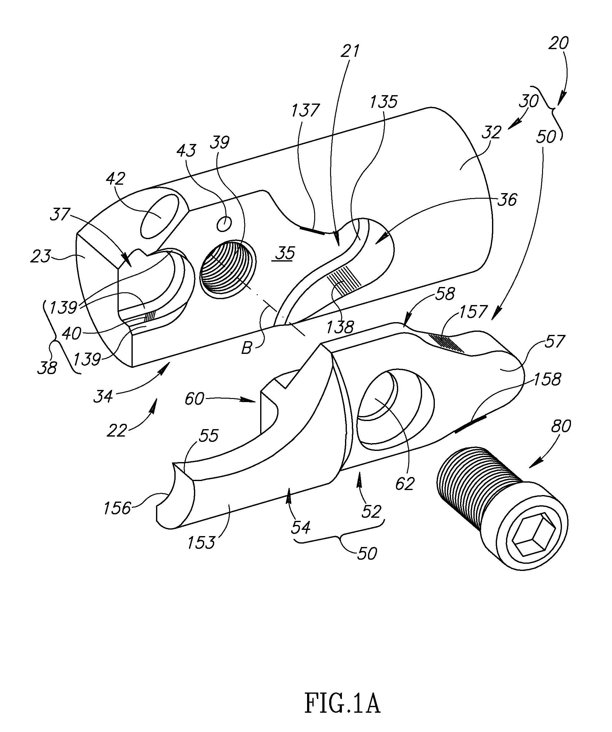
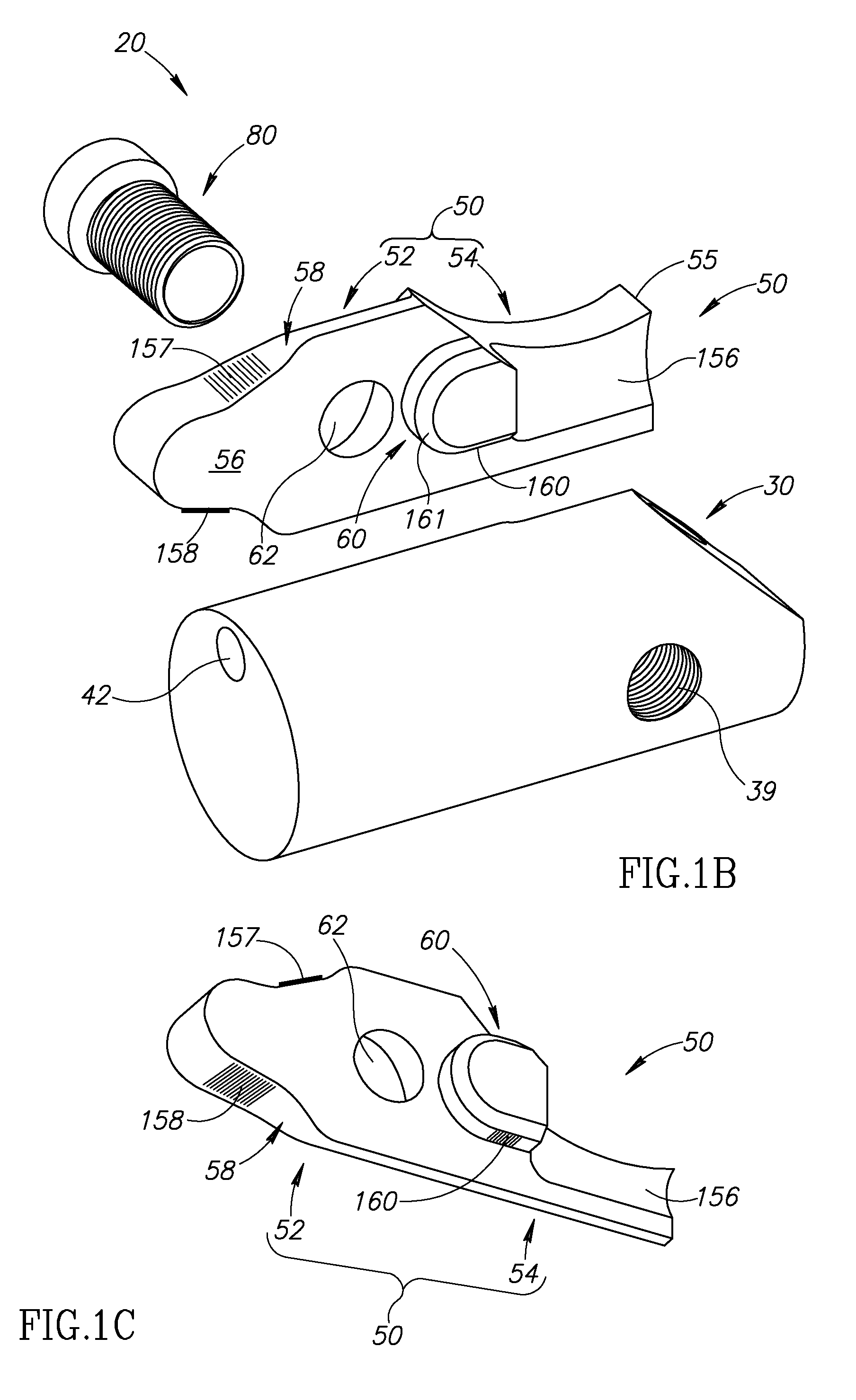
[0042]FIGS. 1A to 2C schematically show perspective exploded views of a cutting tool 20 comprising a tool body 30 and a cutting insert 50, in accordance with an embodiment of the invention. The tool body 30 may be made of a first hard material and the cutting insert 50 of a second hard material that is harder than the first hard material. For example, the tool body 30 may be made of steel and the cutting insert 50 may be made of a hard metal such as, for example, a cemented carbide. The tool body 30 may have a circularly cylindrical cross section. FIGS. 1A and 1B respectively show cutting tool 20 from a side of tool body 30 on which cutting insert 50 is mounted and from a side of the tool body opposite to that on which the cutting insert is mounted. By way of example, cutting insert 50 may be a face-grooving insert. The cutting tool 20 has a longitudinal axis A defining a front to rear direction of the cutting tool 20. The longitudinal axis A may be an axis of rotation of the cuttin...


PUM


Abstract

A cutting tool has a tool body and a cutting insert releasably retained in a pocket of the tool body. The cutting insert has first and second rear insert abutment surfaces and a third forward insert abutment surface and the pocket has first and second rear pocket abutment surfaces and a third forward pocket abutment surface. The first and second abutment surfaces are separated from the third abutment surface by a bore. The third forward pocket abutment surface can be either a socket recessed in a pocket base surface or a protrusion protruding from the base surface; and the third forward insert abutment surface can be correspondingly either a protrusion protruding from an inner surface of the insert or a socket recessed in the inner surface.

Description

FIELD OF THE INVENTION[0001]The invention relates to cutting tools having a tool body with a replaceable cutting insert mounted therein.BACKGROUND OF THE INVENTION[0002]Cutting tools used to shape a surface of a work piece in milling, turning or grooving operations may comprise a replaceable cutting insert that is mounted at an end of a relatively long, rod-like tool body or insert holder. The tool body has a cutting portion having an insert pocket for mounting the cutting insert therein and a shank at an end opposite to the cutting portion for securing the cutting tool in a tool holder of a machine tool.[0003]In a face-shaping or face-grooving operations, a surface at an end of the work piece that is usually substantially perpendicular to the axis about which the work piece rotates is, respectively, shaped and / or formed with a groove. The surface being shaped or grooved may be an internal surface, relatively deep inside the work piece and a groove being formed in a surface may be a...

Claims


Application Information

Patent Timeline
IPC IPC(8): B23B27/16
CPCB23B27/007B23B27/1622B23B29/043B23B29/046B23B2200/165Y10T407/2276B23B2260/112B23B2220/126Y10T407/23Y10T407/2272B23B2260/072
Inventor HECHTKERTSMAN, OLEG
Owner ISCAR LTD
Features
  • Generate Ideas
  • Intellectual Property
  • Life Sciences
  • Materials
  • Tech Scout
  • Unparalleled Data Quality
  • Higher Quality Content
  • 60% Fewer Hallucinations
Learn More