System and method for vertebral body plating

a technology of vertebral body and plate, applied in the field of orthopedic medicine, can solve the problems of difficult to fix plate difficult to create and maintain compression, and difficulty in fixing a straight or flat bone apposition surface to the vertebral surfa

Inactive Publication Date: 2009-02-05
STRYKER EURO OPERATIONS HLDG LLC
View PDF23 Cites 71 Cited by
  • Summary
  • Abstract
  • Description
  • Claims
  • Application Information

AI Technical Summary

Problems solved by technology

Compression may be difficult to create and to maintain.
If a bone screw feature is used to create the compression, backout of the bone screw can be a common problem, as the screw may work its way backwards

Method used


Image

  • System and method for vertebral body plating
  • System and method for vertebral body plating
  • System and method for vertebral body plating

Examples


Embodiment Construction

[0040]The present invention relates to systems and methods for fixation of spinal vertebrae. Those of skill in the art will recognize that the following description is merely illustrative of the principles of the invention, which may be applied in various ways to provide many different alternative embodiments.

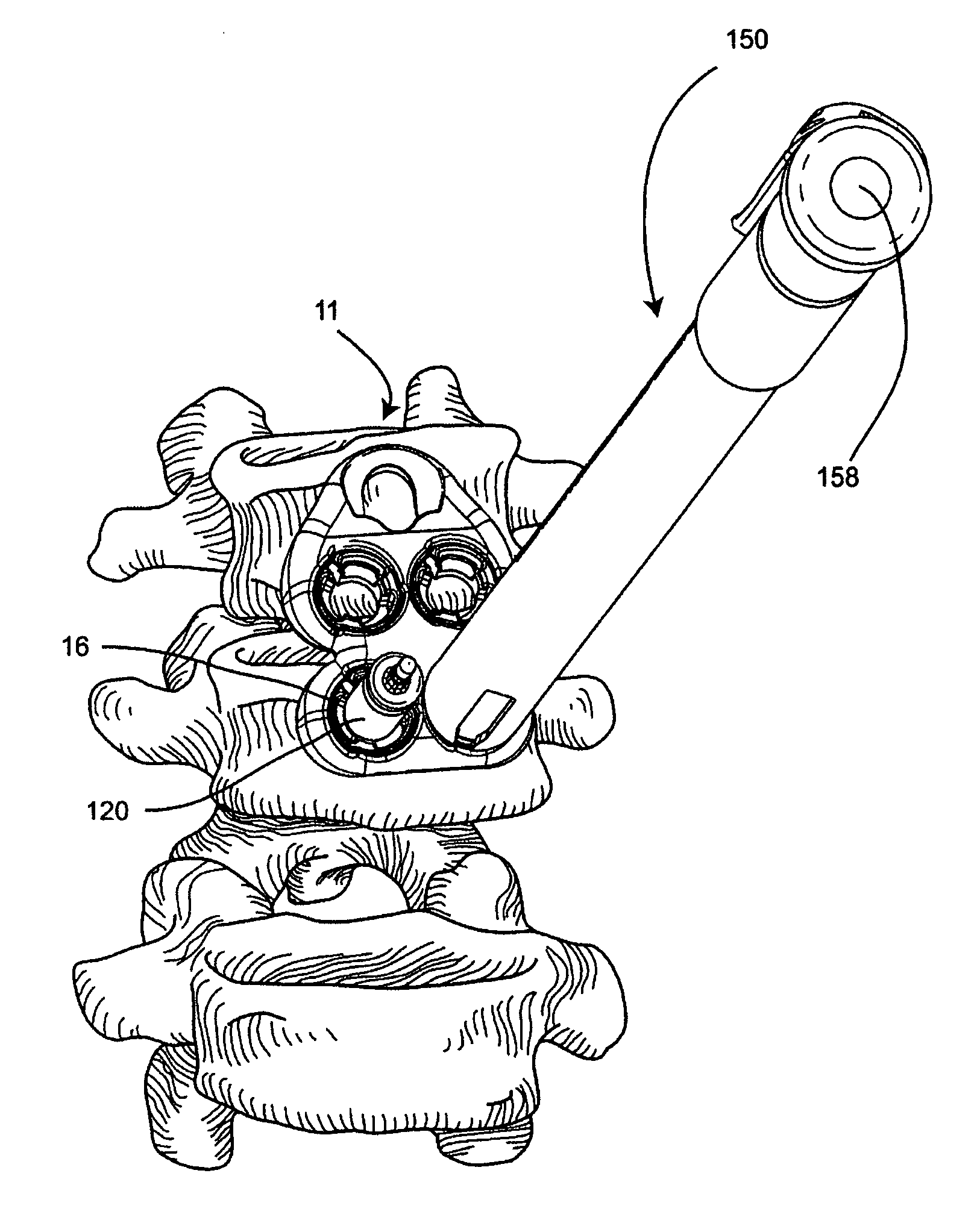
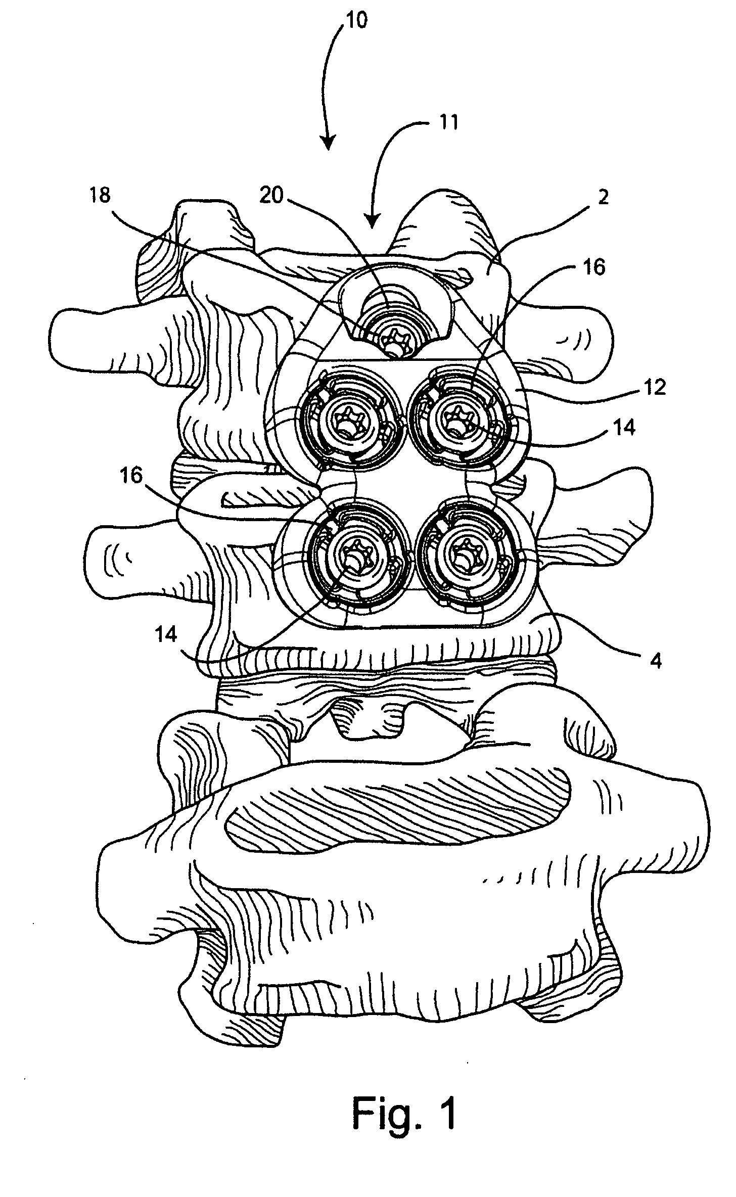
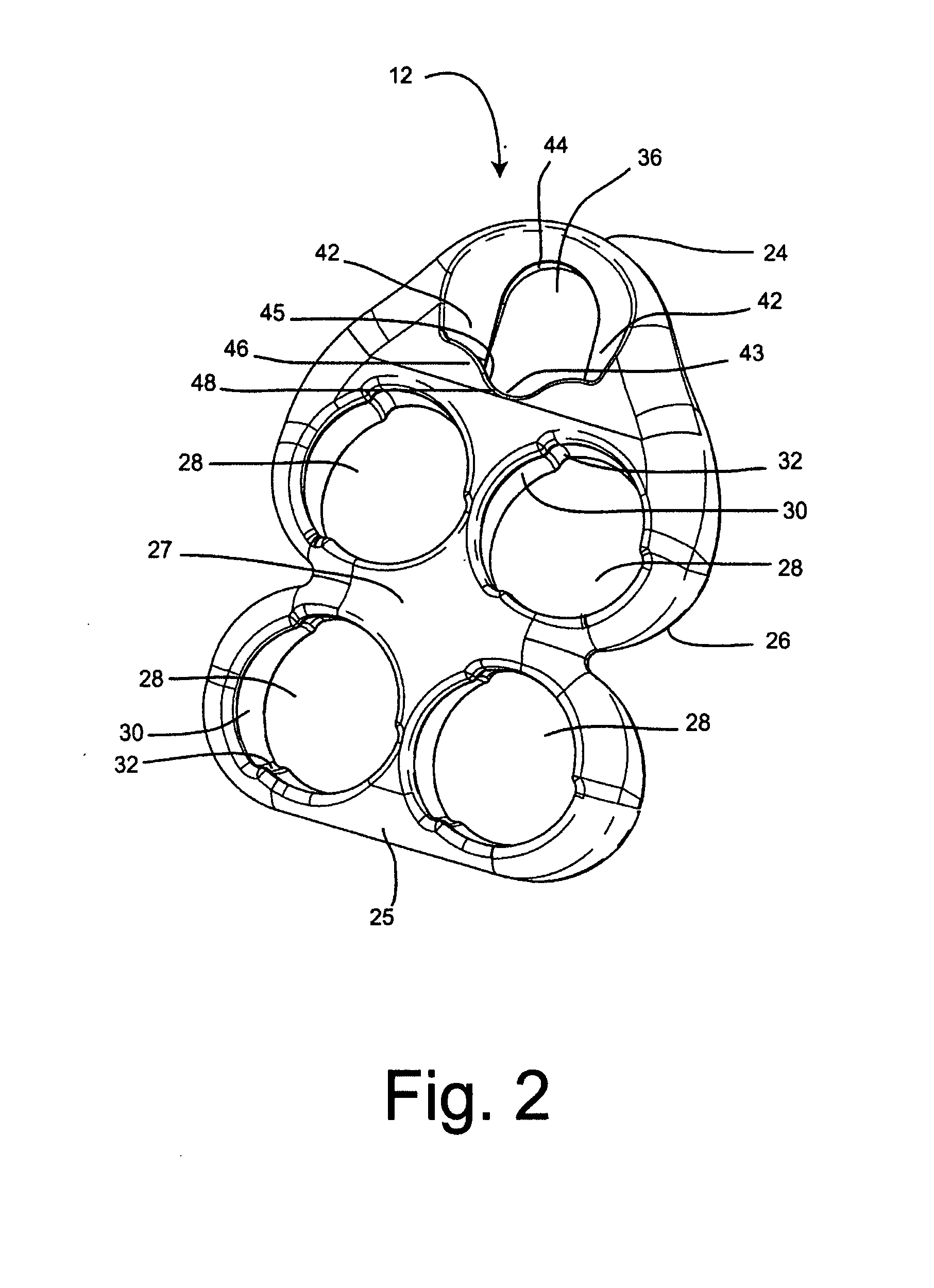
[0041]Referring to FIG. 1, a lumbar plate system 10 is shown attached to the anterior side of a first vertebra 2 and a second vertebra 4. The lumbar plate system 10 comprises a plate assembly 11, a plurality of fixation members 14, and a compression screw 18 with a compression insert 20. The plate assembly 11 comprises a lumbar plate 12 and a plurality of polyaxial locking rings 16. For the purposes of this invention, a compression screw is a device that functions to create and maintain compressive force between vertebrae. The term compression screw does not refer to a unique configuration or shape of the screw but only the function of the screw. Bone screws already known to th...


PUM


Abstract

A spinal plating system for vertebral fixation includes a plate, a compression screw, multiple fixation members and polyaxially adjustable locking rings. The plate is shaped to conform to the curvature of the spine and the surfaces of the vertebral bodies. The compression screw fits through an insert, and together they are guided by the plate as the screw is driven into one of the vertebrae, producing compression between the adjacent vertebrae. A retaining lip on the plate prevents backout of the compression screw. The polyaxial locking rings can be polyaxially pivoted to attain a desired orientation, and are lockable to the plate to maintain the orientation. The fixation members fit through openings in the polyaxial locking rings and the plate to fix the plate to the vertebrae. Locking the polyaxial locking rings fixes the position of the fixation members relative to the plate, and prevents backout of the fixation members.

Description

BACKGROUND OF THE INVENTION[0001]The present invention generally relates to orthopedic medicine, and more particularly to systems and methods for spinal fixation.[0002]Spinal plate systems are commonly used to fix adjacent vertebrae when treating spinal fractures or disorders, and for fusion of vertebrae.[0003]In some instances it is desirable to create compression between adjacent vertebrae, to enhance the bone to graft apposition and provide for better fusion. Compression may be difficult to create and to maintain. If a bone screw feature is used to create the compression, backout of the bone screw can be a common problem, as the screw may work its way backwards out of the bone. Backout prevention features have been designed which are complicated mechanisms with multiple parts. It would be desirable to have a compression screw retention feature which is a monolithic part of the bone plate.[0004]Another important aspect of bone plating systems is the orientation of the fixation mem...

Claims


Application Information

Patent Timeline
IPC IPC(8): A61B17/70A61B17/56A61B17/04A61B17/58
CPCA61B17/1604A61B2019/462A61B17/1671A61B17/1728A61B17/1735A61B17/1757A61B17/68A61B17/7055A61B17/7059A61B17/8014A61B17/8047A61B17/8052A61B17/808A61B17/8615A61B17/863A61B17/8695A61B17/8875A61B2019/303A61B2019/446A61B17/1655A61B90/94A61B2090/033A61B2090/062
Inventor DUBE, MICHAEL A.MARCIANO, FREDERICKPORTER, RANDALLTHEODORE, NICHOLASTRUUMEES, EERICMCDONNELL, CHRISTOPHERJUSTIN, DANIEL F.LEWIS, CHAD W.
Owner STRYKER EURO OPERATIONS HLDG LLC
Why Eureka
Try Eureka