Method and device for an inner-tube

Inactive Publication Date: 2009-02-12
BIBAS BERTY
View PDF7 Cites 11 Cited by
  • Summary
  • Abstract
  • Description
  • Claims
  • Application Information

AI Technical Summary

Benefits of technology

[0026]The inflation tube and deflation tube are to avoid the tedious ta

Problems solved by technology

It is not possible with present technology to have a rubber based pneumatic tire of normal thi

Method used


Image

  • Method and device for an inner-tube
  • Method and device for an inner-tube
  • Method and device for an inner-tube

Examples


Example

[0042]As will be appreciated the present invention is capable of other and different embodiments than those discussed above and described in more detail below, and its several details are capable of modifications in various aspects, all without departing from the spirit of the invention. Accordingly, the drawings and description of the embodiments set forth below are to be regarded as illustrative in nature and not restrictive.

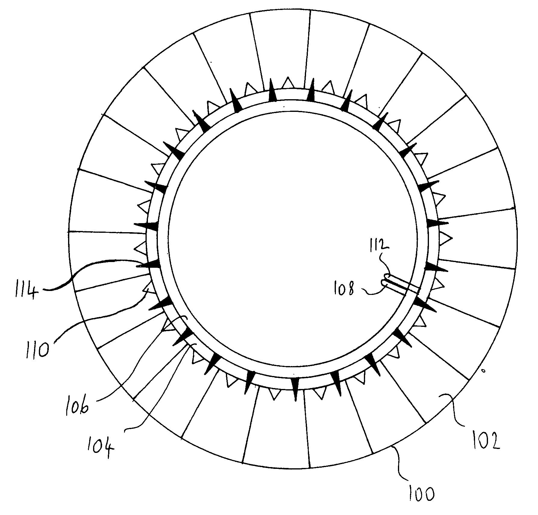
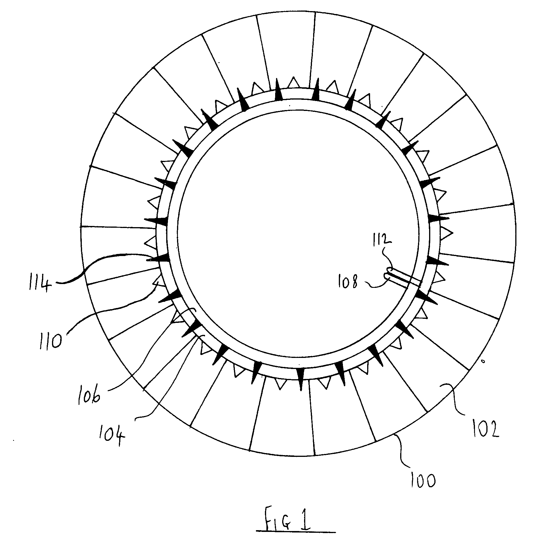
[0043]FIG. 1 shows an inner-tube of this invention 100 whose outer section is divided into many cells 102. There are two more small sized tubes adjacent to the main tube 102, namely the inflation tube 104 and the deflation tube 106. The inflation tube 104 is for filling the inner-tube with air. The air pump connection main valve 112 is capable of being coupled with an air pump that would pump in air to the inflation tube 104 and from there the air would flow through the one way valves 110 into the individual cells 102. The one way valves 110 allow air to enter...


PUM


Abstract

An inner-tube divided into many isolated cells of air. Two tubes on inside circumference of said inner-tube, one for inflating air and the other for deflating air. Each cell has two one-way valves, one for filling air and the other for extracting air. The inflating valve could have an observation window or an air pressure gauge attached to it for indicating when there is a puncture in one or more of the cells of air in the inner tube.

Description

FIELD OF THE INVENTION[0001]This invention is in the field of pneumatic tires and in particular an inner-tube that will not lose all its air when punctured.BACKGROUND OF THE INVENTION[0002]The phenomenum of punctures in pneumatic tires is well known. The problems and dangers involved with punctures in tires applies to tubeless tires and tires with inner-tubes. When even a small hole punctures an inner-tube, the inner-tube usually loses all its air in a very short time. Tubeless tires lose their air slower when the hole is small but larger holes or gashes can cause the air to leave the tire in a few seconds. This presents a number of problems that may be divided into three main categories namely, safety, convenience and costs.[0003]Some of the safety problems of the inner-tube are;[0004]a. Accidents including fatal accidents caused by people changing the flat tire at the side of the road or other dangerous place where passing traffic does not see or can not see a person at the edge o...

Claims


Application Information

Patent Timeline
IPC IPC(8): B60C5/20
CPCY10T152/1054B60C5/20
Inventor BIBAS, BERTY
Owner BIBAS BERTY
Why Eureka
Try Eureka