Image forming apparatus and method for forming image

a technology which is applied in the field of image forming apparatus and image forming method, can solve the problems of not being able to reduce costs, and achieve the effects of reducing memory capacity, reducing cost, and reducing capacity

Inactive Publication Date: 2009-02-12
SHINKO ELECTRIC CO LTD
View PDF3 Cites 4 Cited by
  • Summary
  • Abstract
  • Description
  • Claims
  • Application Information

AI Technical Summary

Benefits of technology

[0006]In the technique of Japanese Patent No. 3861293, because the laminate memory stores therein not data for the whole surface of the recording medium but partial pattern data as described above, the capacity of the memory can be reduced in comparison with the case of storing the data for the whole surface. However, although the capacity can be reduced, a dedicated memory for storing pattern data for transparent film lamination must be provided in the printer. There is a problem that the cost can not be reduced due to the provision of the memory.

Problems solved by technology

There is a problem that the cost can not be reduced due to the provision of the memory.

Method used


Image

  • Image forming apparatus and method for forming image
  • Image forming apparatus and method for forming image
  • Image forming apparatus and method for forming image

Examples


first embodiment

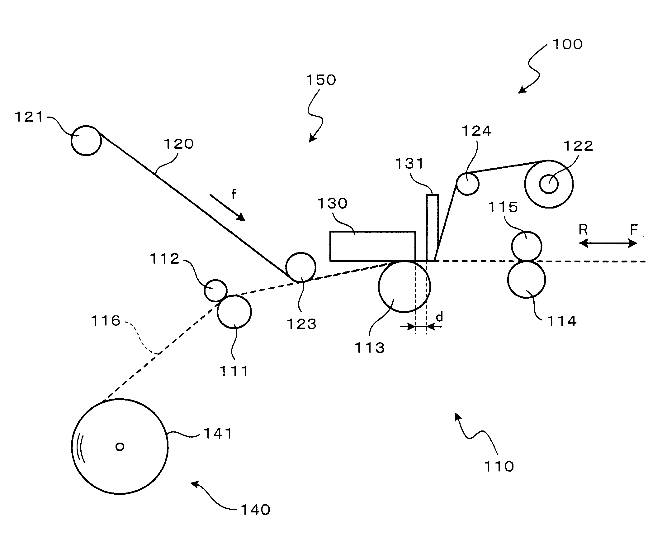
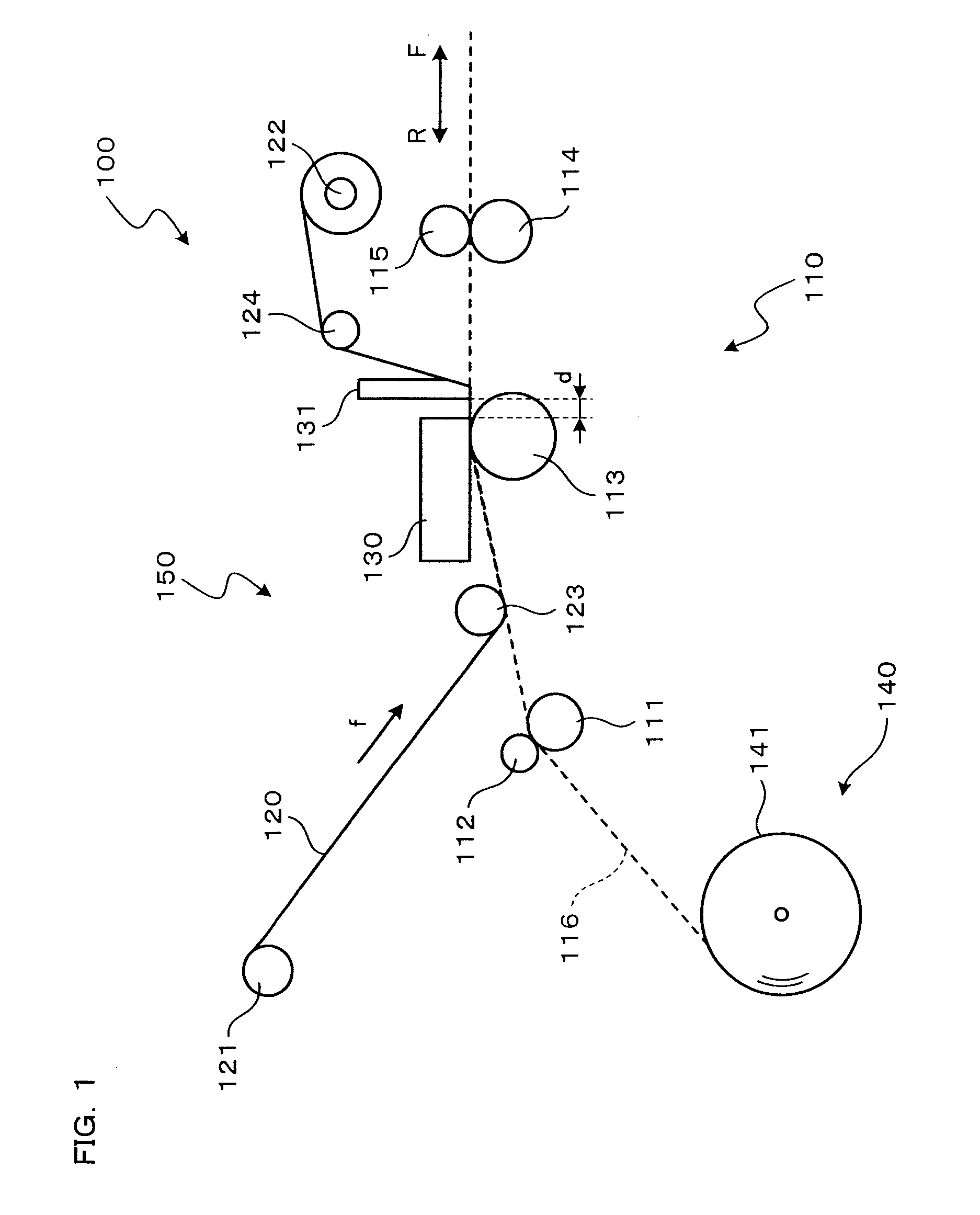
[0030]Hereinafter, preferred embodiments of the present invention will be described with reference to the drawings. As shown in FIG. 1, a thermal transfer printer 100 according to the present invention includes a paper holder 140, a paper conveyance mechanism 110, an ink ribbon conveyance mechanism 150, and a thermal head 130. The thermal transfer printer 100 is connected with a host computer (not shown), and performs image recording on the basis of image data sent from the host computer.

[0031]The paper holder 140 can hold a rolled long paper 141. The paper 141 held by the paper holder 140 is conveyed through a paper conveyance path 116 to the paper conveyance mechanism 110.

[0032]The paper conveyance mechanism 110 includes, in the order from the upstream of the paper conveyance path 116, a feed roller 111 and a pinch roller 112; a platen roller 113 disposed so as to be opposed to the thermal head 130; and a discharge roller 114 and a pinch roller 115. The paper 141 taken out from th...

second embodiment

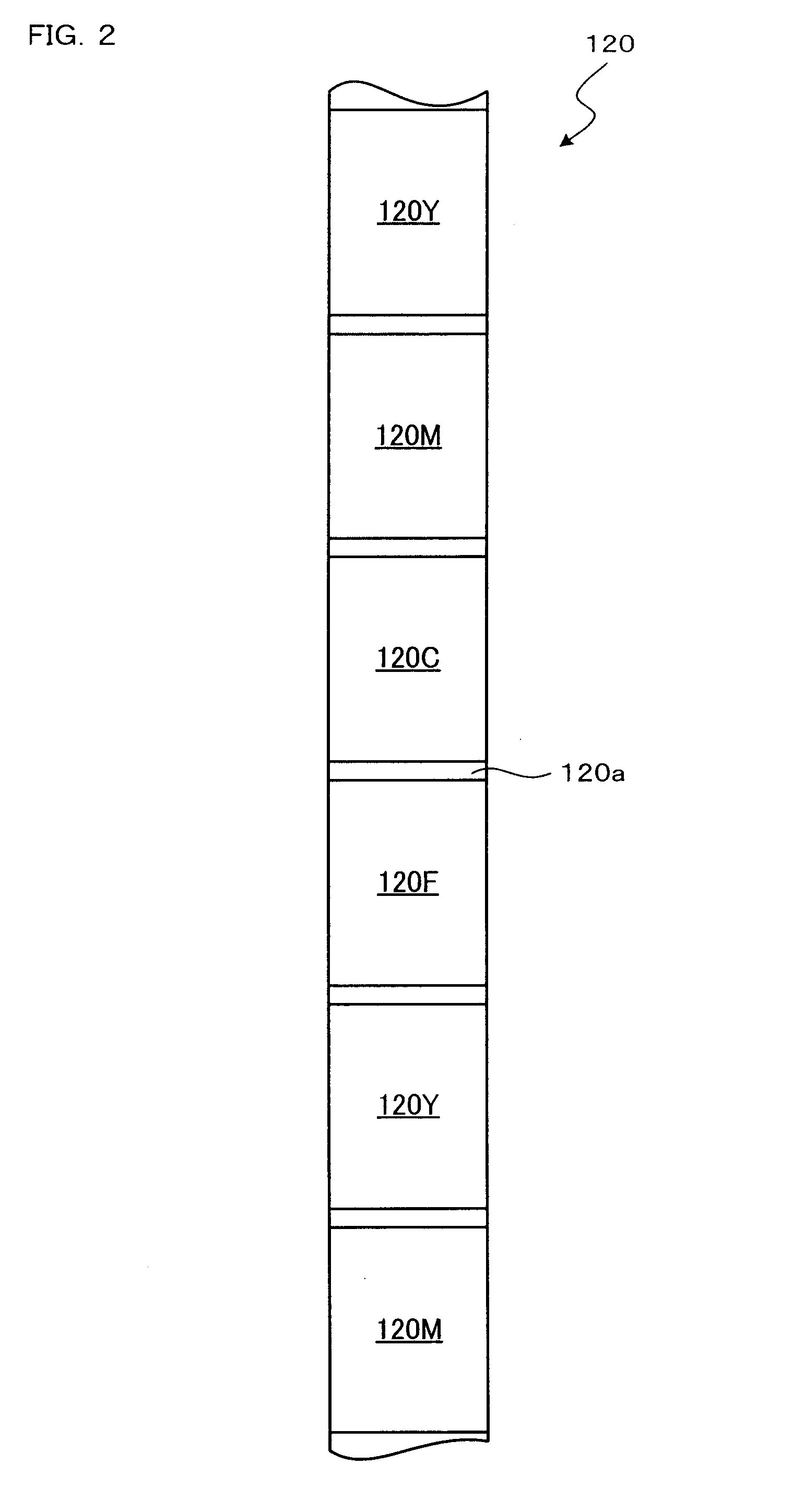
[0049]the present invention will be described. First, an electrical constitution of a thermal transfer printer 100 will be described with reference to FIG. 5. In this embodiment, the same components as in FIG. 3 are denoted by the same reference numerals as in FIG. 3, respectively, and the description thereof will be omitted. As shown in FIG. 5, a color controlling DSP 32 includes a random pattern data generating module 33 that generates random pattern data to be used for transfer of a transparent film 120F. The random pattern data generating module 33 includes a random number generating section 33a, a tone data obtaining section 33b, an image processing section 33c, and a transferring section 33d. The functions of those sections 33a, 33b, 33c, and 33d will be described later in detail with reference to the flowchart of FIG. 6.

[0050]Next, laminate processing will be described with reference to FIG. 6. The following process is performed under the control of the CPU 10.

[0051]First, th...


PUM


Abstract

Data concerning a transfer pattern of lamination transparent film is not externally sent and stored in a memory but generated by a random pattern generating module of a color controlling DSP 22. A random number generating section 23a generates a pseudorandom number for each dot of one line; a tone data obtaining section 23b obtains tone data corresponding to the pseudorandom number; and a transferring section 23c transfers the tone data to a head signal converting ASIC 24. Tone data for each dot of one line is alternately written in line buffers 1 and 2. Using the tone data written in the line buffers 1 and 2, a thermal head 130 transfers transparent film 120F.

Description

BACKGROUND OF THE INVENTION[0001]1. Field of the Invention[0002]The present invention relates to an image forming apparatus and an image forming method, in particular, using a laminate technique.[0003]2. Description of Related Art[0004]As one of image forming apparatuses, a sublimation type thermal transfer printer is known in which color inks of yellow, magenta, and cyan are made to sublimate by heat of a thermal head to form a color image on a recording medium. On the other hand, laminate techniques are known in which the surface of a recording medium on which an image has been formed is coated with a transparent film in order to protect the image formed on the recording medium against moisture and oil to keep the quality of the image for a long time. Such techniques are categorized into gross finish in which a transparent film is transferred to the whole surface in an even pattern; and mat finish in which a transparent film is transferred to the whole surface in an uneven pattern...

Claims


Application Information

Patent Timeline
Patent Type & Authority Applications(United States)
IPC IPC(8): H04N1/60
CPCB41J2/36B41J2/325H04N1/60
Inventor INAGAKI, TSUTOMUTOBA, TAKAYUKIICHII, JUNORIMO, SHINYAHIRAI, YOSHIKAZU
Owner SHINKO ELECTRIC CO LTD
Why Eureka
Try Eureka