Eureka AIR delivers breakthrough ideas for toughest innovation challenges, trusted by R&D personnel around the world.

Multi-color display device

a display device and multi-color technology, applied in the field of multi-color display devices, can solve the problem of not disclosing the operation of the display device, and achieve the effects of reducing the amount of data to be transmitted, reducing the capacity of the memory for storing, and reducing the load of signal processing

Active Publication Date: 2009-01-29
JAPAN DISPLAY INC +1
View PDF12 Cites 36 Cited by
  • Summary
  • Abstract
  • Description
  • Claims
  • Application Information

AI Technical Summary

Benefits of technology

[0011]The multi-color display device according to the present invention is capable of displaying a color image with M types of colors with a reduced amount of data to be transmitted, a reduced capacity of a memory for storing image data and a reduced load of signal processing. The multi-color display device can be achieved with a circuit configuration having a reduced size. In addition, the multi-color display device can be operated with reduced power consumption by reducing the amount of data to be transmitted to reduce the number of times of changes in signals in the circuit. Furthermore, the multi-color display device is provided with the means for converting the compressed color signal into M types of color signals to improve the quality of an image.

Problems solved by technology

JP-B-1994-7688, however, does not disclose operations of a display device, which are required for the method.

Method used


Image

  • Multi-color display device
  • Multi-color display device
  • Multi-color display device

Examples


first embodiment

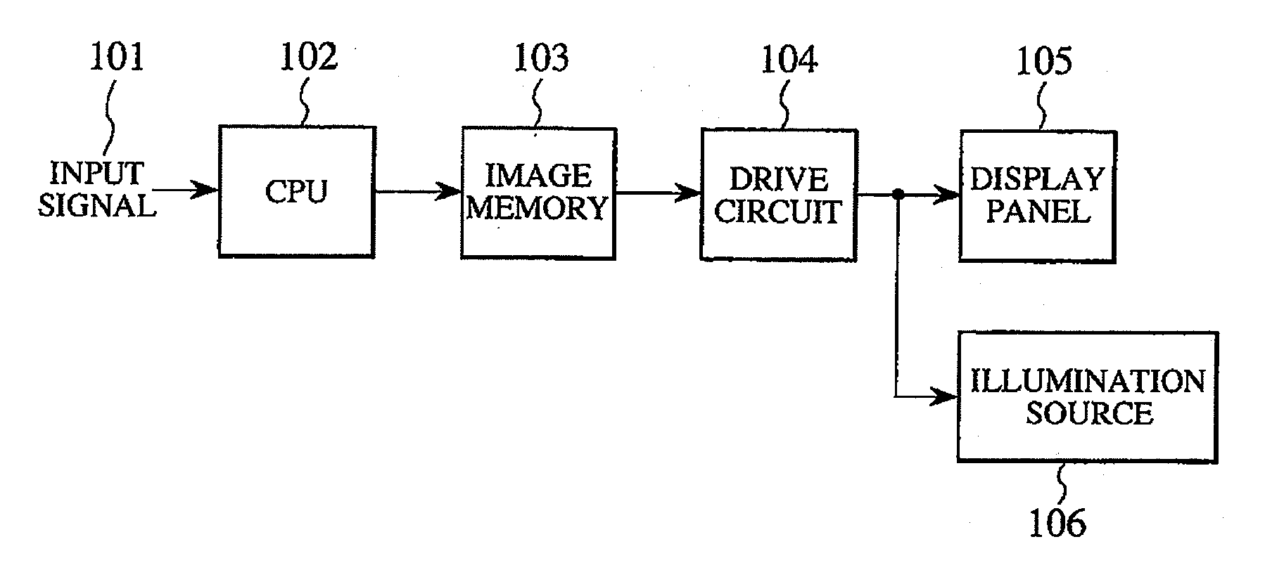
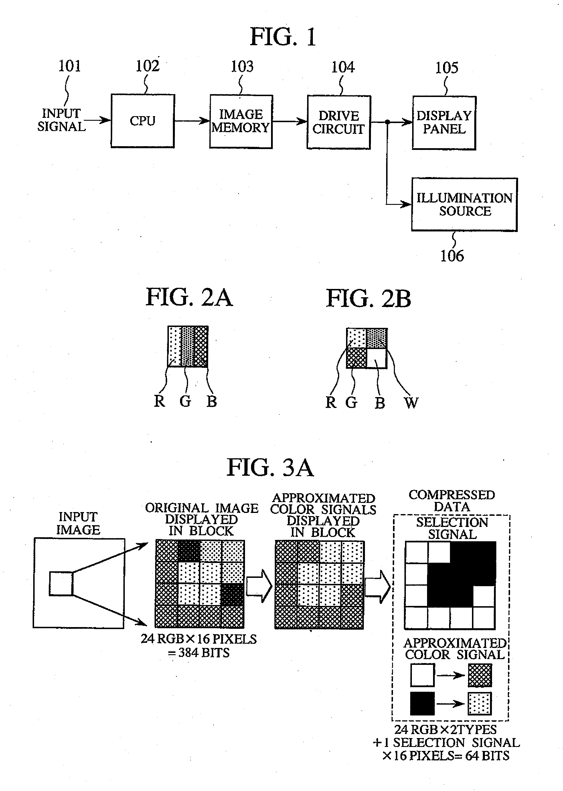
[0031]FIG. 1 is a diagram showing a basic configuration of a multi-color display device according to a first embodiment of the present invention. In FIG. 1, an input signal 101 may be picture data, a character code, a draw command, or the like. The signal 101 is input by taking an image with a camera, or through a network, an input operation with a keyboard by a user, or the like. The input signal 101 is interpreted by a central processing unit (CPU) 102 and converted into bitmap data based on an image size, a bit width per pixel and the like. The bitmap data created in the above way is stored in an image memory 103 and read by a drive circuit 104. The bitmap data then forms an image by driving a display panel 105 and an illumination source (backlight) 106. In the multi-color display device, the display panel 105 is a liquid crystal panel. The display panel 105, however, may be another panel based on the display principle. When the display panel 105 is composed of a liquid crystal e...

second embodiment

[0078]In general, signals to be used for display are generated and obtained by any method. The characteristics of the signals are therefore various. In the second embodiment of the present invention, the characteristic of an image is divided into two types (a picture and a character symbol). The picture includes an image taken by a camera, a design drawing, and some noise. The picture has different types of colors for each pixel. The character symbol is bitmap data converted in accordance with a command, and has a certain limited number of colors representing an image. When the display device has a unit for generating a character symbol by using a command group such as a character code and Hypertext Markup Language (HTML), the picture and the character symbol can be discriminated from each other after the generation of the character symbol.

[0079]The name of a color is led by combining certain RGB color signals. Thus, RGB color signals can be obtained based on the name of the color. ...

third embodiment

[0093]It is general that the outline of a character symbol is important. This is apparent from the fact that a large number of types of fonts are prepared and used in the printing technology field. The outline of a character symbol is formed by a combination of pixels arranged in a plane in a display device, which is different from typical printing techniques. When an oblique line (with respect to a side of an upper surface of a pixel) is included in the outline of a character symbol and is formed by a combination of pixels, the outline of the character symbol includes a fine staircase pattern.

[0094]In the present embodiment, the outline of a character symbol is formed on the basis of a sub-pixel constituting a part of a pixel. This improves the quality of an image. Processing for forming the smooth outline of a character symbol is called smoothing processing. Data on character fonts is written in a read only memory (ROM) in advance. Necessary data is read from the ROM by converting...


PUM


Abstract

It is expected to increase the size of a display panel and the number of tones to be displayed on the display panel, and it is requested to use a display panel displaying M (M>3) types of colors. This requires a large memory capacity and makes a circuit for performing signal conversion complex due to an increase in the amount of data to be subjected to the signal conversion. An image memory stores image data compressed at a fixed compression rate, and the signal conversion is performed on the compressed image data. This technique reduces a memory capacity and simplifies a signal conversion circuit. The signal conversion makes it possible to improve color reproducibility of an image displayed and the quality of the image due to smoothing of the outline of the image. In the case of a display panel having sub-pixels displaying M types of colors, the signal conversion is performed on a compressed signal for each sub-pixel to improve the quality of an image.

Description

BACKGROUND OF THE INVENTION[0001]1. Field of the Invention[0002]The present invention relates to a multi-color display device capable of compressing color image data to store the compressed color image data in an image memory.[0003]2. Description of the Related Art[0004]Human beings recognize color and brightness with three types of visual cells each having different spectral sensitivity by converting external light into three types of electrical signals and determining the color and brightness based on the combination of the three types of electrical signals. According to the human visual characteristics, a color image display device displays a color image by combining three primary colors. Red (R), green (G), and blue (B) colors are used as the primary colors. Any combination of the three colors can be represented as a point located in a three-dimensional space. In general, specifying a point in the three-dimensional space requires three different types of signals.[0005]To display...

Claims


Application Information

Patent Timeline
Patent Type & Authority Applications(United States)
IPC IPC(8): G06T9/00G06T1/60
CPCG09G3/3406G09G5/026G09G2340/02G09G2340/0457H04N19/40H04N19/12H04N19/14H04N19/48H04N19/426H04N19/176
Inventor INUZUKA, TATSUKI
Owner JAPAN DISPLAY INC
Why Eureka
Eureka Blog
Learn More