

Adaptation of transmit power based on maximum received signal strength
Active Publication Date: 2009-02-12
QUALCOMM INC
View PDF40 Cites 79 Cited by
- Summary
- Abstract
- Description
- Claims
- Application Information
AI Technical Summary
Benefits of technology
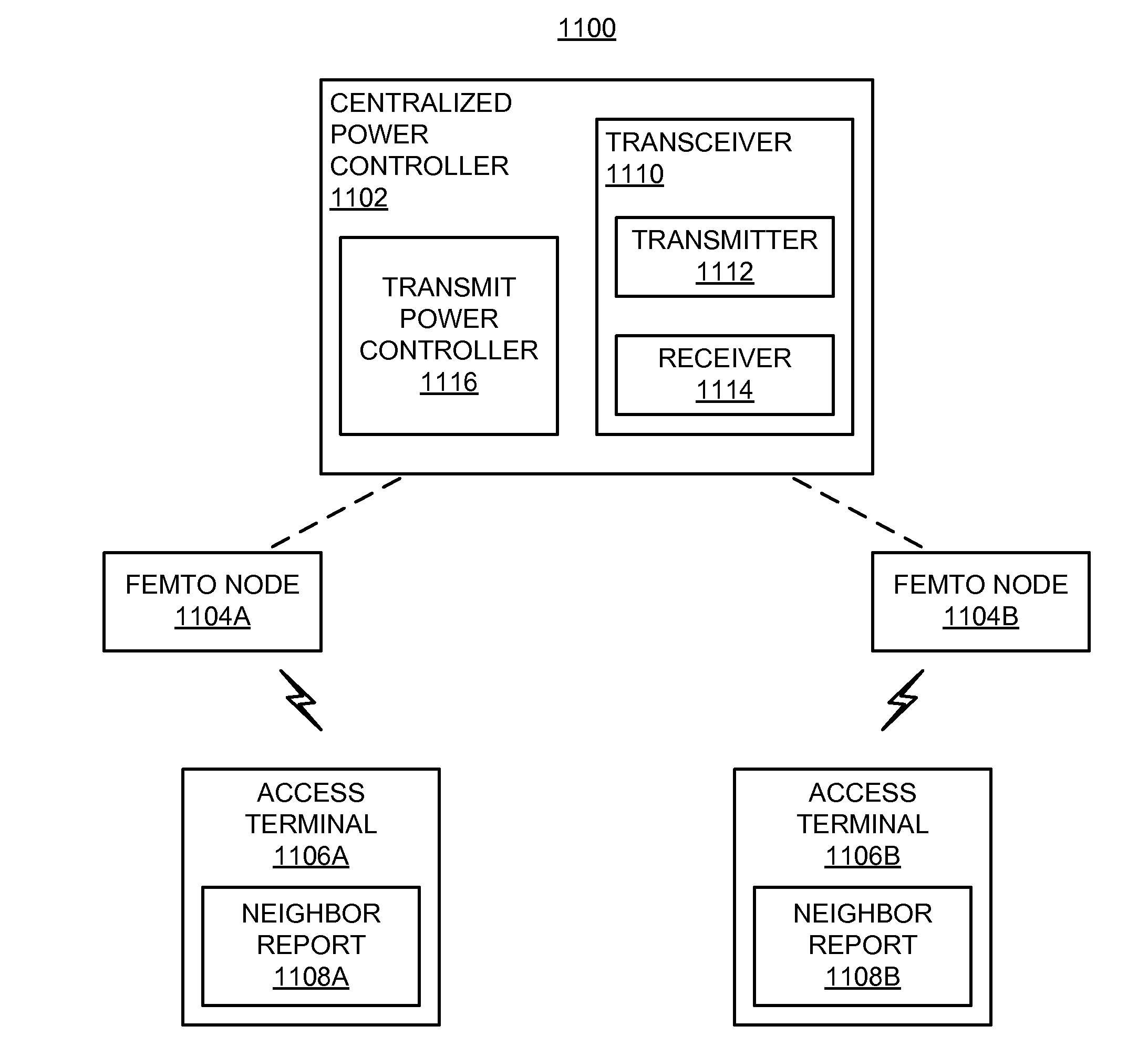
[0017]The disclosure relates in some aspects to adaptively adjusting the downlink transmit power of neighboring access nodes. In some aspects, sharing of information between access nodes may be utilized to enhance network performance. For example, if an access terminal is experiencing high interference levels from a neighboring access node, information relating to this interference may be relayed to the neighbor access node via the home access node of the access terminal. As a specific example, the access terminal may send
Problems solved by technology
As the demand for high-rate and multimedia data services rapidly grows, there lies a challenge to implement efficient and robust communication systems with enhanced performance.
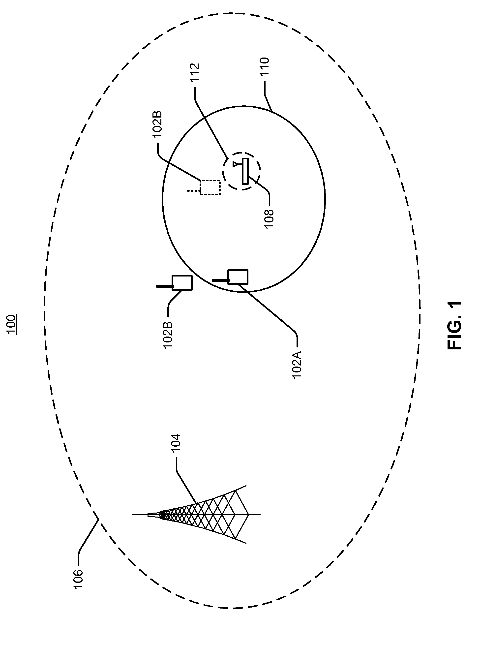
Consequently, femto cells may cause interference both on the uplink (“UL”) and downlink (“DL”) of the macro cells.
For example, a femto base station installed near a window of a residence may cause significant downlink interference to any access terminals outside the house that are not served by the femto cell.
Also, on the uplink, home access terminals that are served by a femt
Method used
View moreImage
Smart ImageViewing Examples

Examples
 PUM
 Abstract
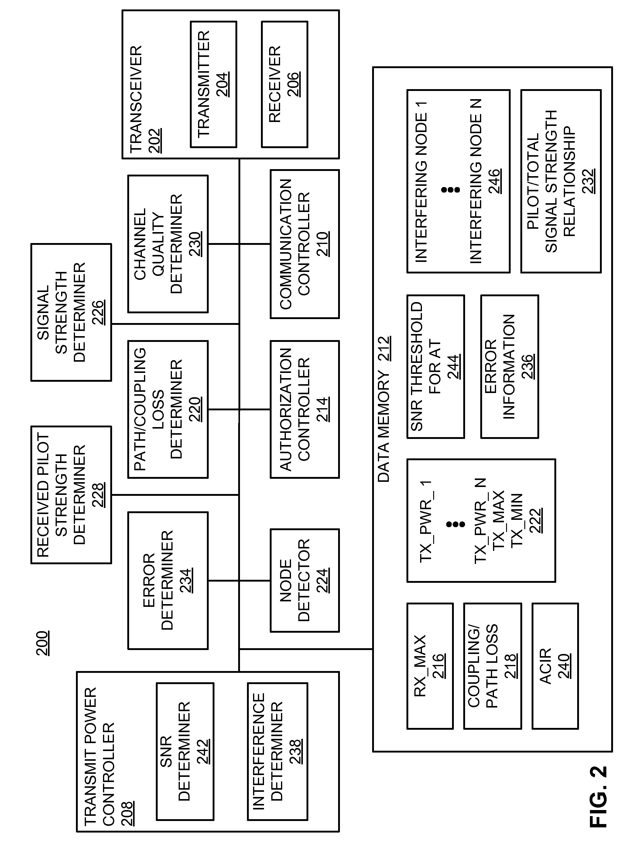
Transmit power (e.g., maximum transmit power) may be defined based on the maximum received signal strength allowed by a receiver and a minimum coupling loss from a transmitting node to a receiver. Transmit power may be defined for an access node (e.g., a femto node) such that a corresponding outage created in a cell (e.g., a macro cell) is limited while still providing an acceptable level of coverage for access terminals associated with the access node. An access node may autonomously adjust its transmit power based on channel measurement and a defined coverage hole to mitigate interference. Transmit power may be defined based on channel quality. Transmit power may be defined based on a signal-to-noise ratio at an access terminal. The transmit power of neighboring access nodes also may be controlled by inter-access node signaling.
Description
CLAIM OF PRIORITY UNDER 35 U.S.C. §119[0001]This application claims the benefit of and priority to commonly owned U.S. Provisional Patent Application No. 60 / 955,301, filed Aug. 10, 2007, and assigned Attorney Docket No. 072134P1, and U.S. Provisional Patent Application No. 60 / 957,967, filed Aug. 24, 2007, and assigned Attorney Docket No. 072134P2, the disclosure of each of which is hereby incorporated by reference herein.CROSS-REFERENCE TO RELATED APPLICATION[0002]This application is related to concurrently filed and commonly owned U.S. patent application Ser. No. ______, entitled “AUTONOMOUS ADAPTATION OF TRANSMIT POWER,” and assigned Attorney Docket No. 072134U2; U.S. patent application Ser. No. ______, entitled “ADAPTATION OF TRANSMIT POWER BASED ON CHANNEL QUALITY,” and assigned Attorney Docket No. 072134U3; and U.S. patent application Ser. No. ______, entitled “ADAPTATION OF TRANSMIT POWER FOR NEIGHBORING NODES,” and assigned Attorney Docket No. 080952; the disclosure of which ...
Claims
Login to View More Application Information
Patent Timeline
 IPC IPC(8): H04B7/26H04W88/00
CPCH04W16/16H04W36/04H04W52/143H04W52/40H04W52/245H04W52/367H04W52/244H04W52/24H04W52/32
InventorYAVUZ, MEHMETBLACK, PETER J.NANDA, SANJIV
OwnerQUALCOMM INC