
Method for Network Co-ordination in a Mobile Communications System and Apparatus Thereof

a mobile communications system and network coordination technology, applied in the field of network coordination in a mobile communications system and apparatus thereof, can solve the problems of inapplicability and inability to integrate co-operative transmission within 3gpp, and achieve the effect of reducing interference, reducing interference among cells, and high capacity of users equipmen

Inactive Publication Date: 2011-12-15
NOKIA SOLUTIONS & NETWORKS OY +1
View PDF23 Cites 79 Cited by
  • Summary
  • Abstract
  • Description
  • Claims
  • Application Information

AI Technical Summary

Benefits of technology

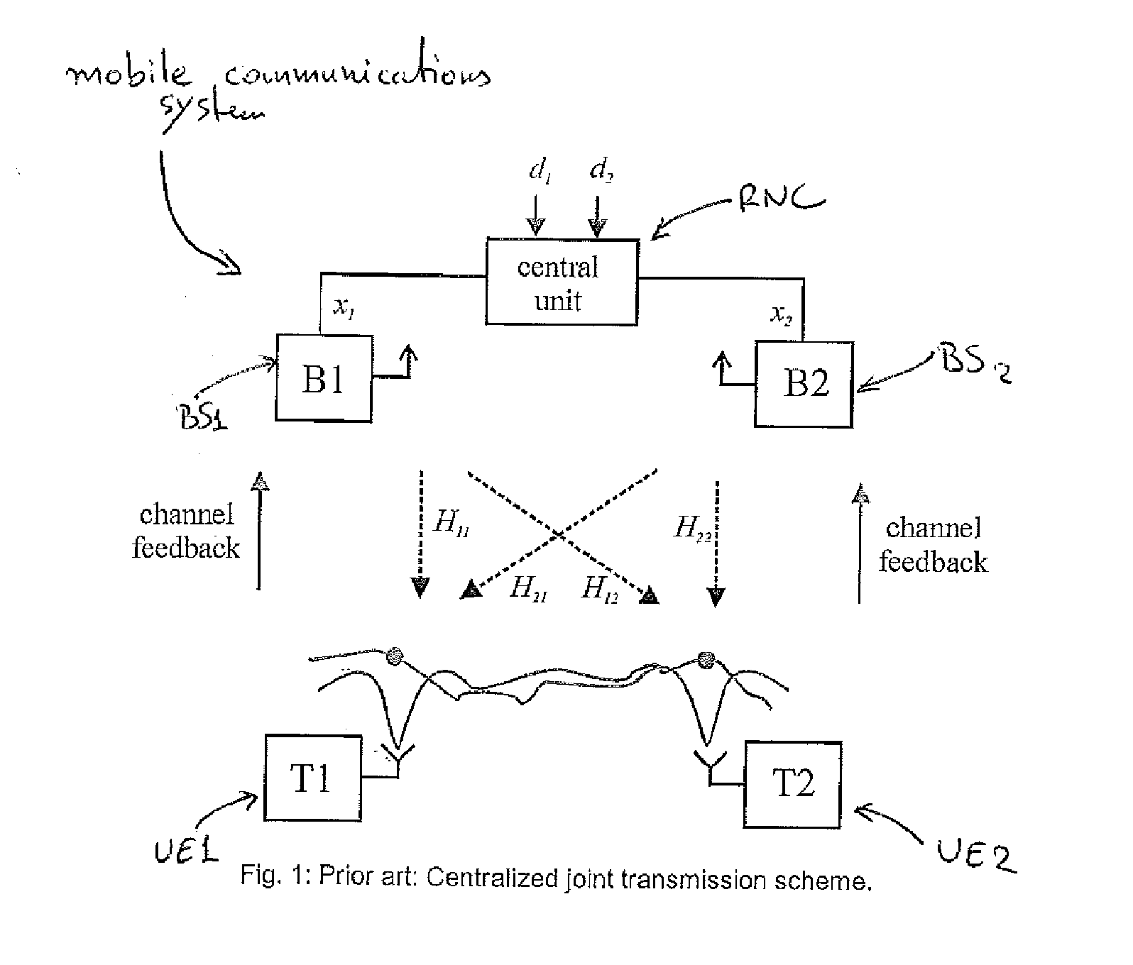
[0002]3G (3rd Generation Wireless Mobile Communication Technology) mobile networks require intensive network planning in order to achieve a high capacity of UEs (User Equipments) and user satisfaction based on pre-determined traffic models, network topology data and networking scenarios. In order to reduce interference caused by the high number of UEs present, co-operative transmission is used. By co-operative transmission it is meant that multiple base stations (BSs) serve jointly a set of user terminals (UEs) scheduled onto the same radio resource in their respective cells, within a mobile communications system. Using co-operative beam-forming at the base stations, interference among the cells can be reduced. For this purpose, the base stations exchange data signals as well as channel state information stemming from feedback of the terminals. Such an implementation is provided by M. K. Karakayali, G. J. Foschini, and R. Valenzuela, “Network Co-ordination for spectrally efficient communications in cellular systems,” IEEE Wireless Communications, vol. 13, no. 4, 2006 and in “3GPP TS 36.300v800, E-UTRA and E-UTRAN—overall description”, March, 2007.
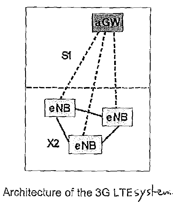
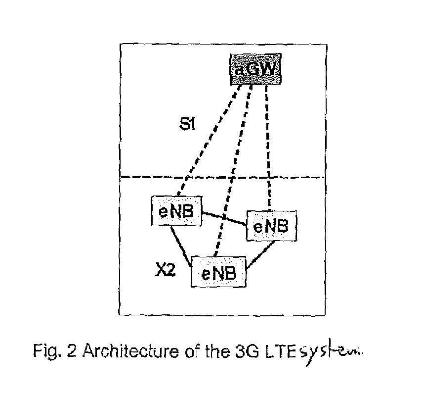
[0006]FIG. 2 depicts a backbone network architecture used in 3GPP LTE. There are two networks between the base stations. Data are delivered from the Internet over an advanced gateway (aGW) to which the base stations (denoted as enhanced nodeBs, eNBs) are connected in a star network using the so-called S1 interface. In addition, eNBs coordinate their transmission over the so called X2 interface. The network establishes an additional meshed network between the eNBs. Both networks can be based on the same infrastructure, i.e. star and meshed networks are just logically separated. A first advantage of this new backbone network architecture is that essential decisions, like the scheduling of radio resources, can be performed closer to the radio channel, i.e. at each base station separately. In this way, channel state information is not so much outdated anymore. Radio transmission can be adapted instantaneously to the time-varying wireless channel, with the goal that even the fast frequency-selective fading can be tracked. Multipath, multiuser and spatial diversity can be realized in this way leading to a significantly improved network performance. More specifically, radio resources can be assigned in which the instantaneous signal-to-interference-and-noise ratio is maximized, and hence the interference between the eNBs is minimized.

Problems solved by technology

However, an efficient integration of co-operative transmission within 3GPP (3rd Generation Partnership Project) LTE (Long Term Evolution) is not that simple as there exist incompatibilities with the backbone structure used in LTE.
This is however not applicable in LTE, because flat IP (internet protocol)-based network architecture is used without an RNC.

Method used


Image

  • Method for Network Co-ordination in a Mobile Communications System and Apparatus Thereof
  • Method for Network Co-ordination in a Mobile Communications System and Apparatus Thereof
  • Method for Network Co-ordination in a Mobile Communications System and Apparatus Thereof

Examples


Embodiment Construction

[0030]The basic principle of the invention is shown in FIG. 3. Rather than using a central unit as in FIG. 1, data are distributed to all cooperative base stations (BSs). Moreover, the superimposed pilots of all base stations (BSs) are received by each user terminal (UE), and the compound channel information from all base stations (BSs) is fed back to the serving base station (BS). Observations are exchanged between the base stations (BS) over the X2 interface, such that the compound multiuser multicell channel matrix can be recovered at each base station (BS) involved in the cooperative transmission. At each base station, there is a local processing unit which computes the locally relevant beam forming weights and applies them to the data streams intended for the user terminals (UEs).

[0031]In order however, to make such distributed co-operative transmission efficient and well integrated within the mobile communications system, further points have also to be clarified. These points ...


PUM


Abstract

Method and Apparatus thereof for coordinating a joint transmission between a plurality of cooperative access nodes serving a plurality of user terminals in a mobile communications system, including the steps of: receiving channel information by said access nodes from user terminals that are being served by said access nodes; exchanging between said access nodes of said received channel information thus ensuring that all channel information is distributed to all cooperative access nodes; processing all received channel information by each one of said access nodes, and determining by said access nodes using said processed channel information, of a channel estimation for said joint transmission.

Description

FIELD OF THE INVENTION [0001]The invention is used in mobile communications systems to ensure that the networks operating therein are co-ordinated and that co-operative transmissions can be effected.SUMMARY OF THE INVENTION[0002]3G (3rd Generation Wireless Mobile Communication Technology) mobile networks require intensive network planning in order to achieve a high capacity of UEs (User Equipments) and user satisfaction based on pre-determined traffic models, network topology data and networking scenarios. In order to reduce interference caused by the high number of UEs present, co-operative transmission is used. By co-operative transmission it is meant that multiple base stations (BSs) serve jointly a set of user terminals (UEs) scheduled onto the same radio resource in their respective cells, within a mobile communications system. Using co-operative beam-forming at the base stations, interference among the cells can be reduced. For this purpose, the base stations exchange data sig...

Claims


Application Information

Patent Timeline
IPC IPC(8): H04W4/00
CPCH04B7/022H04B7/0617H04B7/026
Inventor FORCK, ANDREASHAUSTEIN, THOMASJUNGNICKEL, VOLKERSCHELLMANN, MALTESCHULZ, EGON
Owner NOKIA SOLUTIONS & NETWORKS OY
Learn More