Coating Film Transfer Tool

Inactive Publication Date: 2009-02-26
FUJI COPIAN
View PDF3 Cites 14 Cited by
  • Summary
  • Abstract
  • Description
  • Claims
  • Application Information

AI Technical Summary

Benefits of technology

[0007]In view of the above problems, the object of the present invention is to provide a coating film transfer tool which is capable of both way of unfailing transfer, spotting transfer by pressing and continuous transfer by pressing and parallel shifting, and which is capable of easy switchover between the two functions.
[0017]Further, according to this invention, the coating film transfer tool has improved handleability, because it is capable of switchover between spotting transfer by pressing and continuous transfer by pressing and parallel shifting with a simple operation of opening and closing the cover member of the sliding body.

Problems solved by technology

However, a first embodiment disclosed in Unexamined Japanese Patent Publication No. 55895 / 1994 lacks user-friendliness, because it requires a user to keep holding down a button which stands out of a rear end of a cylindrical case.
Further, since a spring which holds the slider is not arranged coaxially with the pressing stick or on a midline of the slider, the pressing stick cannot be moved into and out of the case smoothly, causing a problem in handling.
However, it is not capable of smooth continuous transfer, because the transfer head has a generally flat surface.
In addition, it leaves following problems in handling; the head member cannot be pressed hard against a receiving surface, because it is supported by elastic force of a spring; the head member is kept exposed, letting the coating film fall off and thus requiring a user to turn a reel to unreel an unused transfer tape before using the tool.

Method used


Image

  • Coating Film Transfer Tool
  • Coating Film Transfer Tool
  • Coating Film Transfer Tool

Examples


Embodiment Construction

[0025]Referring to the drawings, an embodiment of this invention is to be described hereafter.

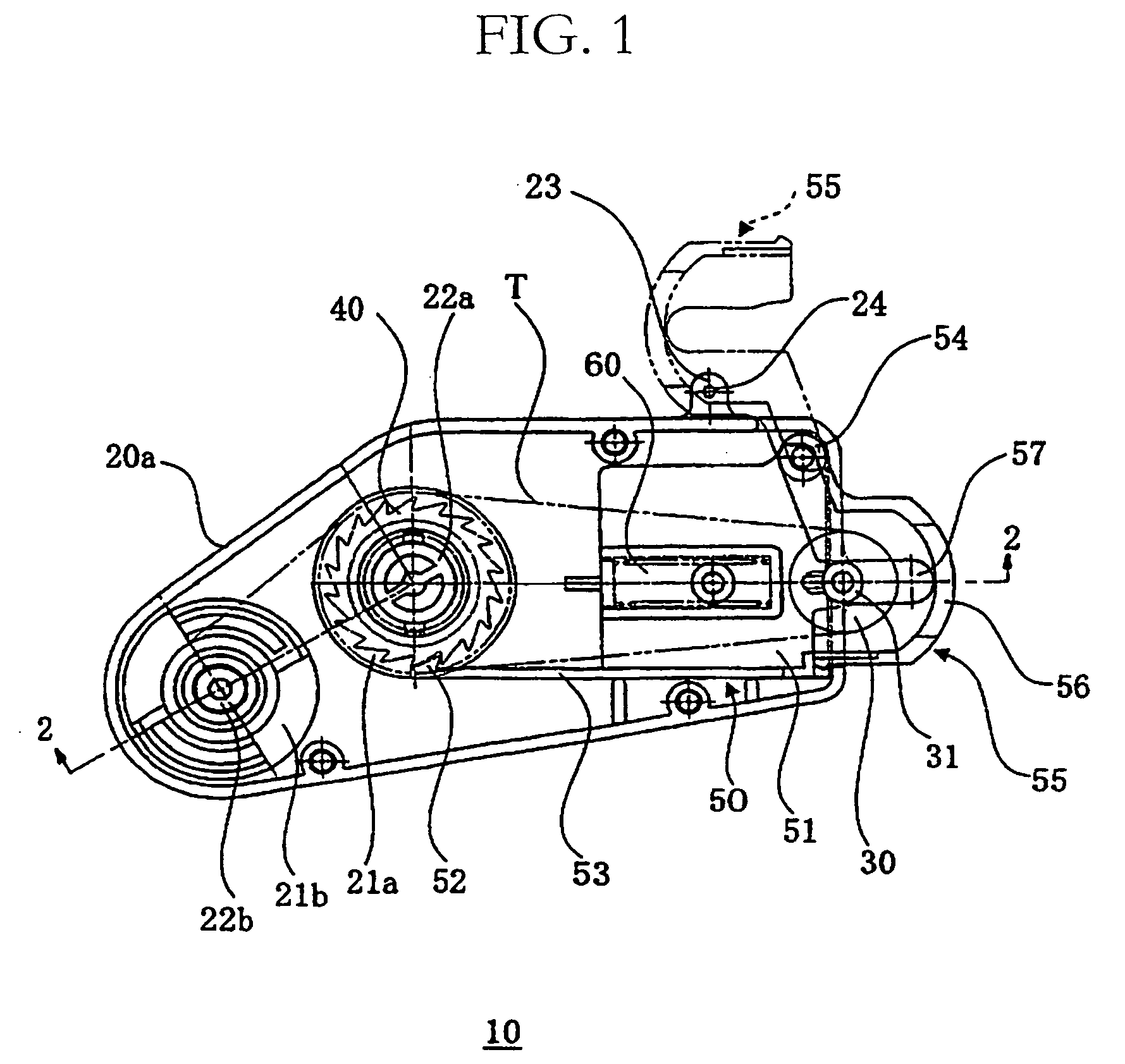
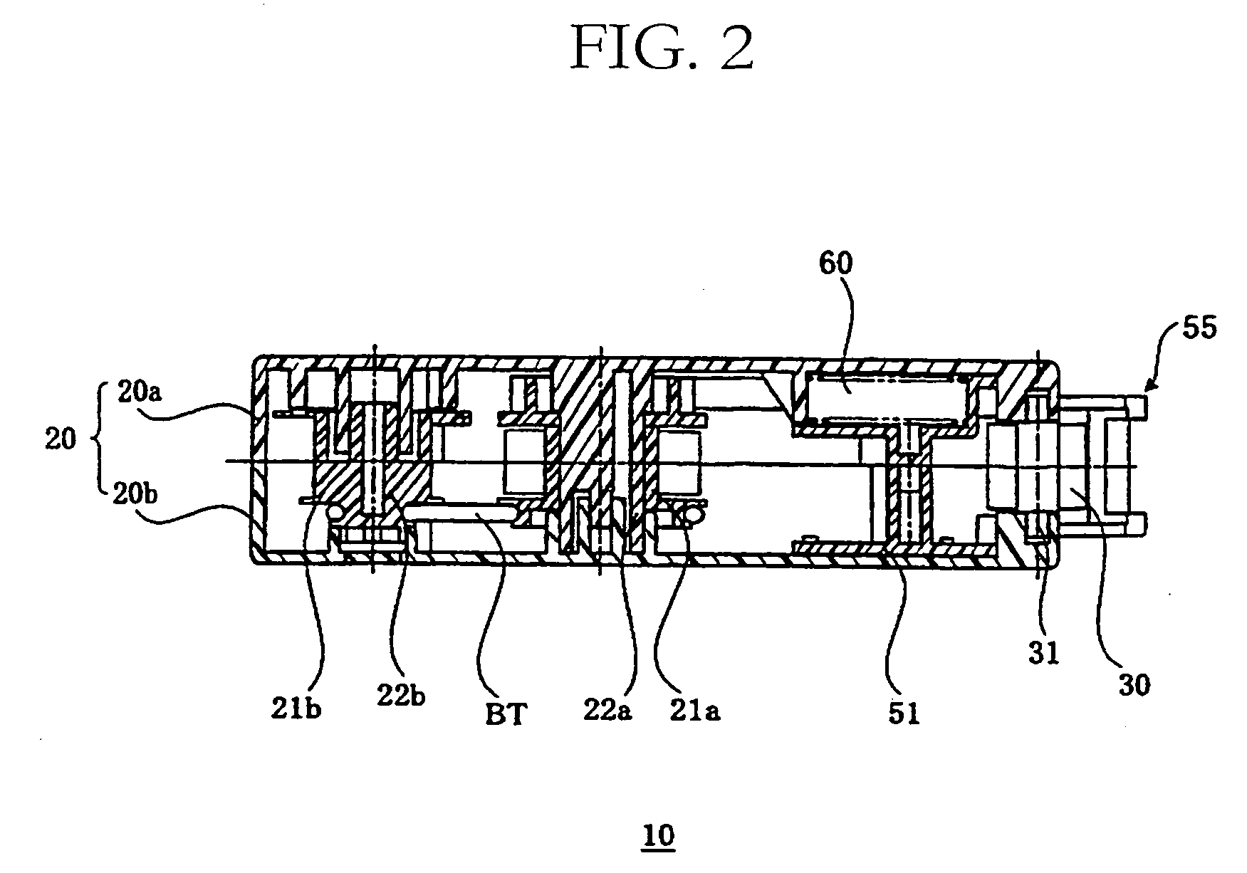
[0026]FIG. 1 illustrates an embodiment of the coating film transfer tool of this invention, which is a top view of the embodiment without a cover 20b. FIG. 2 is a sectional view of FIG. 1 along the line 2-2. FIG. 3 is a right side view of FIG. 1, and FIG. 4 is an opposite side view of FIG. 1.

[0027]FIG. 5 illustrates the embodiment being used for spotting transfer, while FIGS. 6 and 7 illustrate the same being used for continuous transfer. For illustrative purpose, FIGS. 5-7 show a casing main body of a coating film transfer tool 10 without the cover 20b.

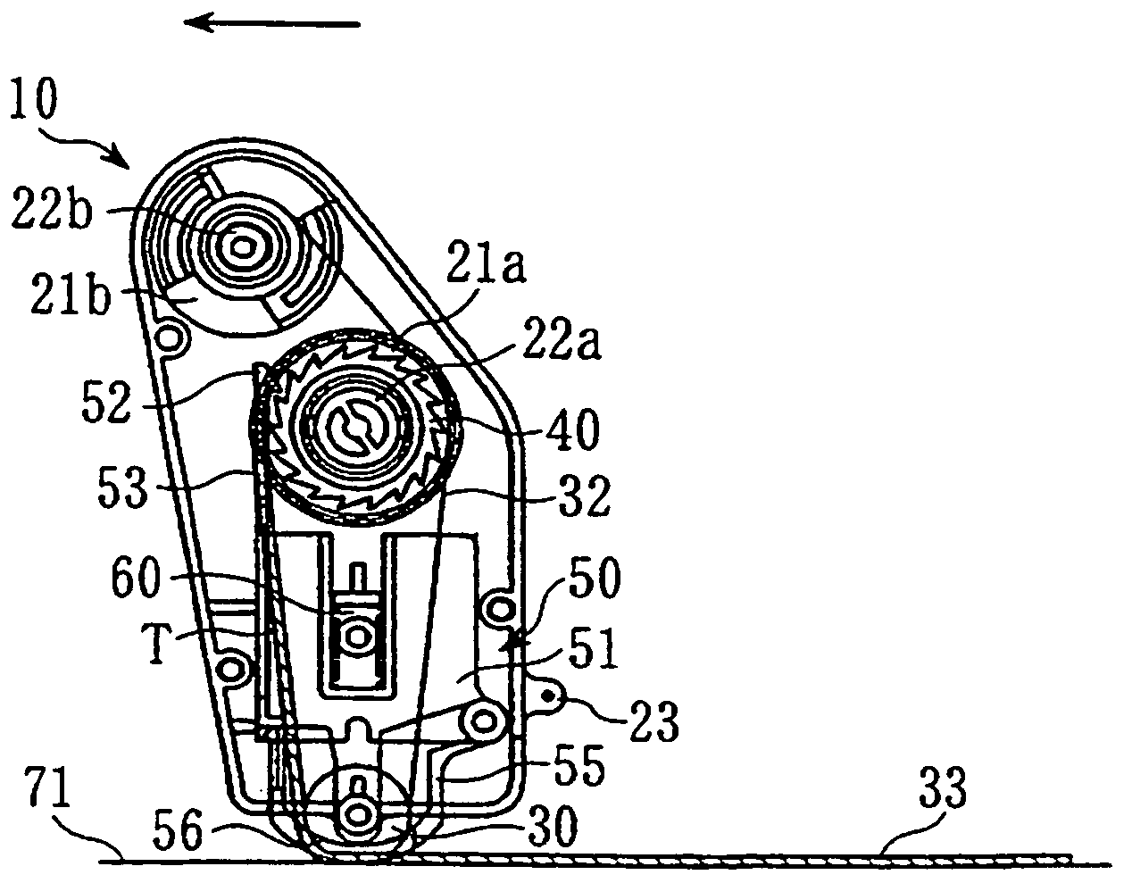
[0028]The coating film transfer tool 10 of the present invention comprises a casing main body 20 composed of a case 20a and the cover 20b, a supply reel 21a which supplies a transfer tape T composed of a base tape and a coating film attached thereon, a transfer head 30 which is arranged at the end of the casing main body 20 and transfers th...


PUM


Abstract

A gear 40 is provided coaxially on a supply reel 21a or a take-up reel 21b. A sliding body 50 which comprises a pawl member 52 which engages with the gear 40 in only one direction and a cover member 55 which houses a transfer head 30 and has an opening 56 is held movable by means of an elastic member 60 within a casing main body 20. The cover member 55 is made openable and closable on the sliding body 50. With the cover member 55 in a closed position, a coating film can be transferred on a spot by pressing the cover member 55 against a receiving surface to cause the sliding body 50 to retreat and by pressing the transfer head 30 against the receiving surface which is pushed out of the opening 56 of the cover member 55, and as the cover member 55 is released from pressing and the sliding body 50 is moved forward, the pawl member 52 rotates the supply reel 21a and the take-up reel 21b in a forwarding direction of the transfer tape. With the cover member 55 in an open position, the coating film can be transferred continuously by pressing the transfer head 30 against and moving it parallel to the receiving surface.

Description

FIELD OF THE INVENTION[0001]This invention relates to a coating film transfer tool for transferring films such as correction films and adhesives onto a receiving surface.BACKGROUND ART[0002]A conventional coating film transfer tools comprises a supply reel and a take-up reel, both rotatably supported within a case having a transfer head, the supply reel having therearound a roll of a transfer film which is composed of a base tape and a coating film attached thereon. The transfer head is pressed against and moved parallel to a receiving surface to transfer the coating film thereon.[0003]A relatively long section of print with 10-15 letters can be easily erased with such a coating film transfer tool. However, when erasing a small section with one or a few letters, it is hard to adjust the length of the transfer tape to just cover the letter(s) to be erased, often transferring the film over or short of the part to be erased. In such a case, coating films have to be removed or added, re...

Claims


Application Information

Patent Timeline
IPC IPC(8): B32B37/10
CPCB43L19/0068Y10T156/1705Y10T156/17B65H37/007
Inventor SAKANISHI, YUTAKA
Owner FUJI COPIAN
Why Eureka
Try Eureka