Tape printing apparatus and tape printing system

a printing apparatus and tape technology, applied in printing, typewriters, other printing apparatus, etc., can solve the problems of unstable detection of attribute information with respect to film tape, difficult attachment and detachment thereof, and possible subtle position deviation of the recessed space with respect to the sensor support portion, so as to improve the handleability and print quality, and facilitate the attachment and detachment of the tape cartridge. , the effect of improving the position accuracy

Inactive Publication Date: 2017-11-21
SEIKO EPSON CORP
View PDF11 Cites 1 Cited by
  • Summary
  • Abstract
  • Description
  • Claims
  • Application Information

AI Technical Summary

Benefits of technology

[0008]An object of the present invention is to provide a tape printing apparatus and a tape printing system in which both smoothness and appropriate positioning accuracy can be realized when the tape cassette is attached and detached.
[0031]According to this configuration, it is possible to smoothly perform attachment and detachment of the tape cartridge, and it is possible to mount the tape cartridge with improved positioning accuracy. Accordingly, it is possible to improve handleability and print quality.

Problems solved by technology

In the print label preparation apparatus of the related art, since the two pin holes corresponding to the two positioning pins and the recessed space corresponding to the sensor support portion are positioned away from each other, there is a concern that subtle positional deviation of the recessed space with respect to the sensor support portion may occur when the tape cassette is mounted.
Accordingly, there is a problem that detection of the attribute information with respect to the film tape is unstable.
However, if the positioning pins and pin holes are accurately formed, a friction resistance increases when the tape cassette is attached and detached, and there is a problem that attachment and detachment thereof are difficult.

Method used


Image

  • Tape printing apparatus and tape printing system
  • Tape printing apparatus and tape printing system
  • Tape printing apparatus and tape printing system

Examples


first embodiment

Details of Detection Portion and Detection Object (First Embodiment)

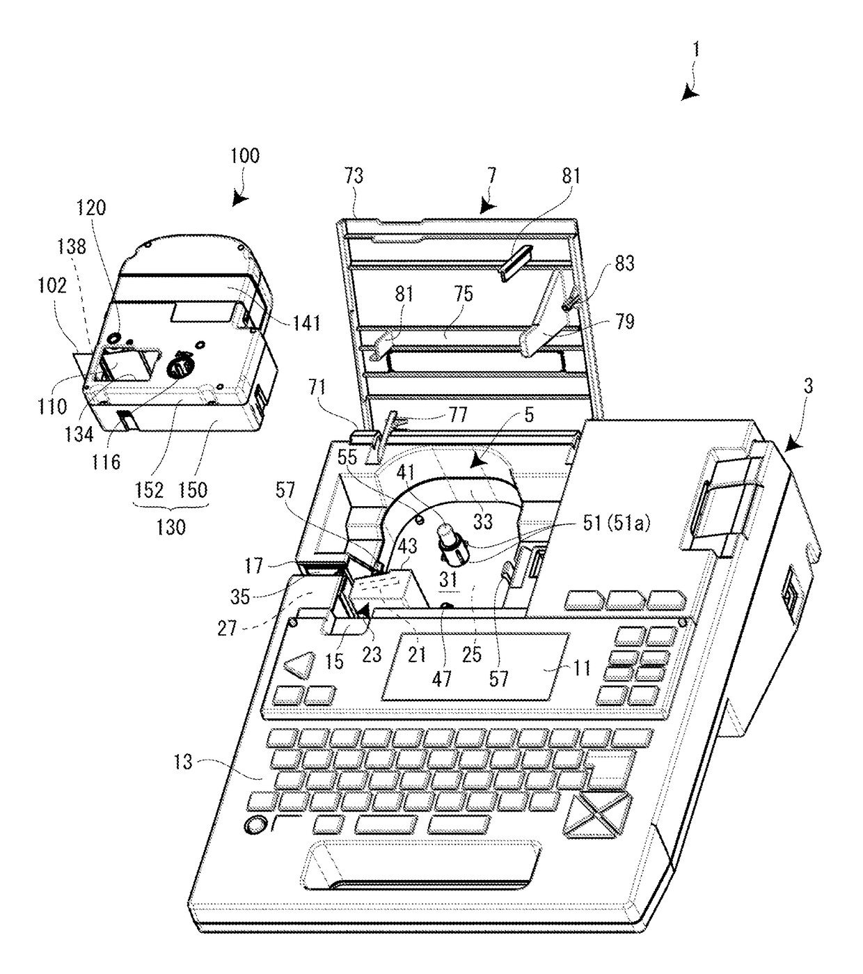
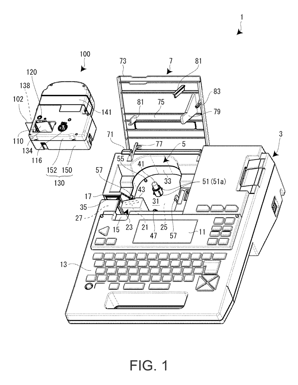
[0090]Next, a structure around the detection portion 51 of the cartridge mounting portion 5 and a structure around the detection object 180 of the tape cartridge 100 are described in detail with reference to FIGS. 7 to 9. FIG. 7 is a perspective view of the cartridge mounting portion 5, FIG. 8 is a perspective view of the lower case 150 of the tape cartridge 100, and FIG. 9 is an enlarged sectional view of portions around the detection portion 51 and the detection object 180 in a state where the tape cartridge 100 is mounted on the cartridge mounting portion 5.

[0091]As shown in the drawings, the detection portion 51 configured of the plurality of (four in the shown example) conductive contactors 51a (spring pieces) is provided on the positioning protrusion portion 41 (engagement projection portion) of the cartridge mounting portion 5. Meanwhile, the detection object 180 is provided on the inner peripheral portion of...

second embodiment

[0126]Next, as a second embodiment, an embodiment in which the conductive contactors 51a are used as simple spring pieces is described. In the second embodiment, portions different from those of the first embodiment are mainly described. In this embodiment, a tape detection portion (not shown) corresponding to the detection portion 51 is provided in the vicinity of the winding drive shaft 47, and a tape detection object (not shown) corresponding to the detection object 180 is provided on the tape cartridge 100 corresponding to the tape detection portion.

[0127]As shown in FIG. 14A, four spring pieces 401 are provided on the positioning protrusion portion 41, and the four spring pieces 401 come into direct contact with the inner peripheral surface of the core shaft portion 192. Each spring piece 401 has the same shape as that of the conductive contactor 51a, and similarly to the first embodiment, the spring pieces 401 are held by a spring holder 403 corresponding to the insulating hol...

third embodiment

[0135]Next, a third embodiment is described with reference to FIG. 15. In the third embodiment, portions different from those of the second embodiment are mainly described.

[0136]As shown in FIG. 15, in the third embodiment, the positioning protrusion portion 41 (second projection portion 302) and a plurality of (four) spring pieces 401B are integrally formed. That is, the four spring pieces 401B are formed by partially removing the peripheral wall in a “U” shape at four locations of the second projection portion 302 in the peripheral direction. Each spring piece 401B includes a plate-shaped spring portion 431 which is suspended from the shoulder portion of the second projection portion 302, and a hemispherical protrusion 433 which protrudes from the outer surface of the lower end portion of the plate-shaped spring portion 431.

[0137]In this case, if the second recessed portion 322 of the core shaft portion 192 is fitted to the second projection portion 302 of the positioning protrusi...


PUM


Abstract

A tape printing apparatus or the like is provided, in which both smoothness and high positioning accuracy can be realized when a tape cartridge is attached and detached. The tape printing apparatus includes a cartridge mounting portion on which a tape cartridge having a core shaft portion disposed on an inner peripheral side of a wound print tape is detachably mounted, a positioning protrusion portion which protrudes from the cartridge mounting portion and engages with an inner peripheral portion of the core shaft portion of the mounted tape cartridge, and a plurality of conductive contactors which are provided in the positioning protrusion portion, in which the plurality of conductive contactors are equally disposed in a peripheral direction in the positioning protrusion portion, and bias an inner peripheral surface of the engaged core shaft portion toward the outside in a radial direction.

Description

CROSS-REFERENCE TO RELATED APPLICATIONS[0001]This application is the U.S. National Phase under 35 U.S.C. §371 of International Application No. PCT / JP2015 / 001546 filed on Mar. 19, 2015, which in turn claims the benefit of Japanese Application No. 2014-060914 filed on Mar. 24, 2014, and Japanese Application No. 2014-157993 filed on Aug. 1, 2014, the disclosures of which are expressly incorporated by reference herein.TECHNICAL FIELD[0002]The present invention relates to a tape printing apparatus and a tape printing system including a cartridge mounting portion on which a tape cartridge is detachably mounted.BACKGROUND ART[0003]In the related art, as this kind of tape printing apparatus, a print label preparation apparatus including a cassette mounting portion is known (refer to JP-2013-141749).[0004]In the cassette mounting portion, a transport mechanism or a printing mechanism which performs printing on a tape discharged from a tape cassette is disposed, and two positioning pins which...

Claims


Application Information

Patent Timeline
Patent Type & Authority Patents(United States)
IPC IPC(8): B41J15/04B41J3/407
CPCB41J3/4075B41J15/044
Inventor SAKANO, HIDEKISHINTANI, AKIHIRO
Owner SEIKO EPSON CORP
Why Eureka
Try Eureka