
Tape printing apparatus and tape printing system
a printing apparatus and tape technology, applied in printing, typewriters, other printing apparatus, etc., can solve the problems of unstable detection of attribute information with respect to film tape, difficult attachment and detachment thereof, and possible subtle position deviation of the recessed space with respect to the sensor support portion, so as to improve the handleability and print quality, and facilitate the attachment and detachment of the tape cartridge. , the effect of improving the position accuracy
- Summary
- Abstract
- Description
- Claims
- Application Information
AI Technical Summary
Benefits of technology
Problems solved by technology
Method used
Image

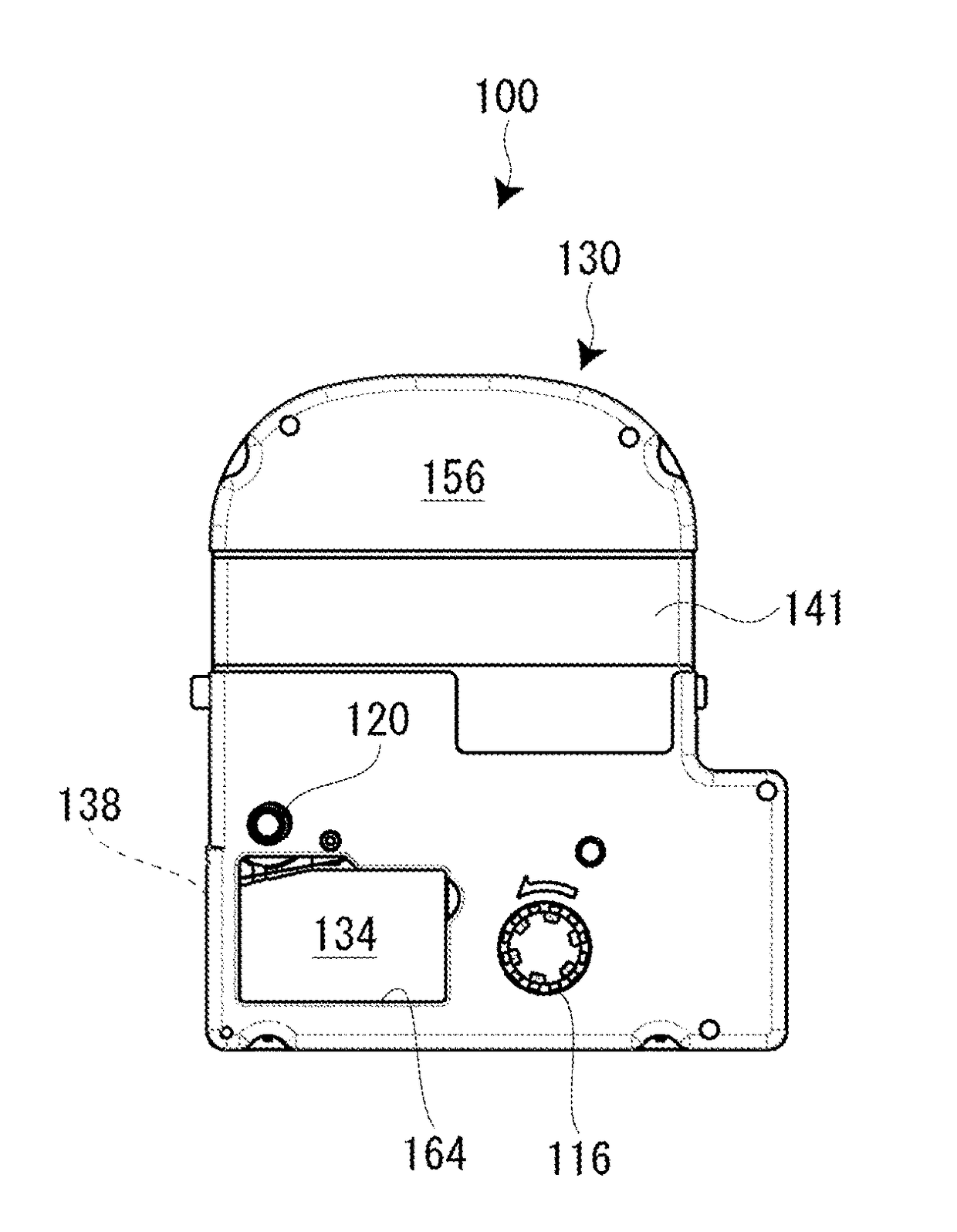
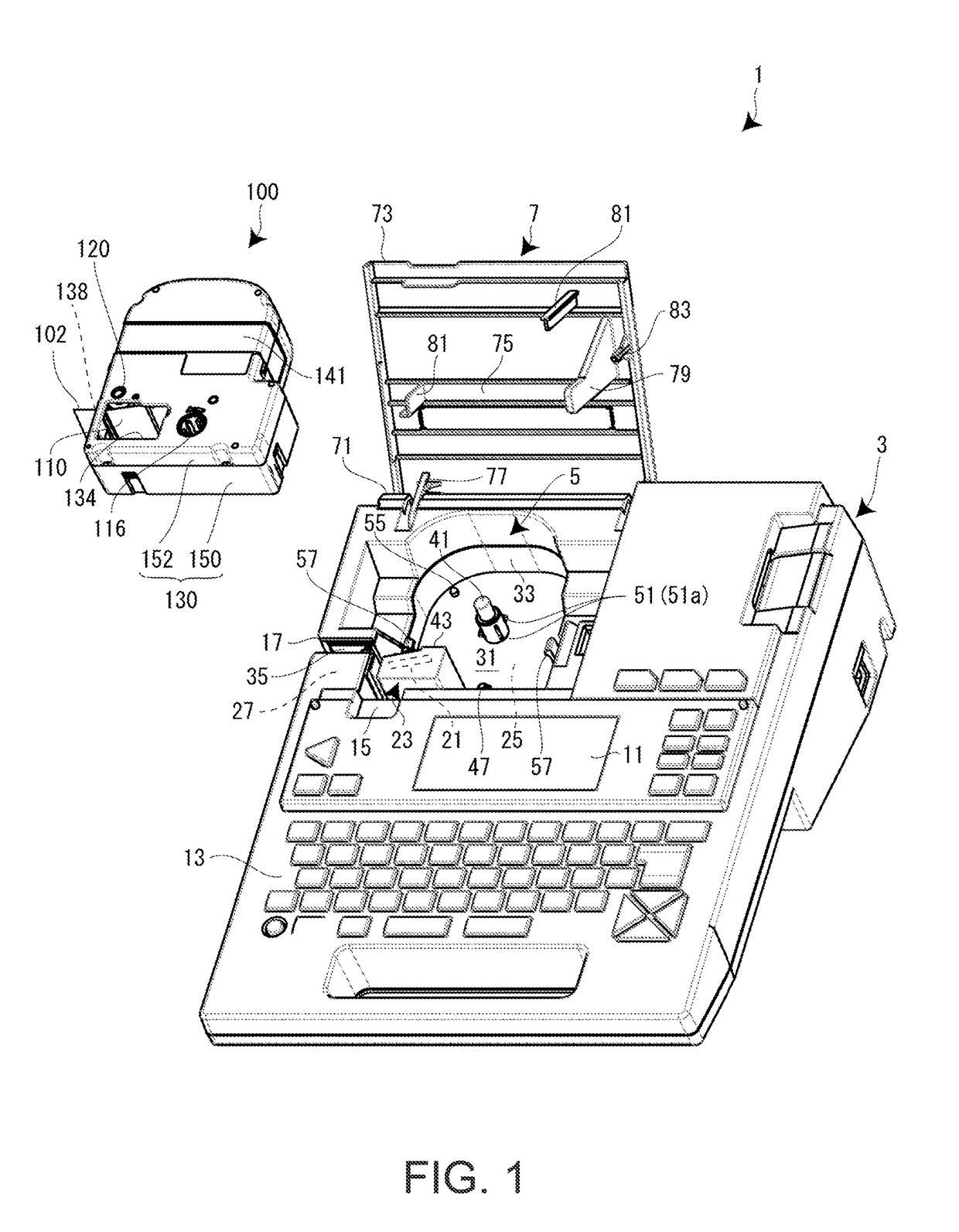
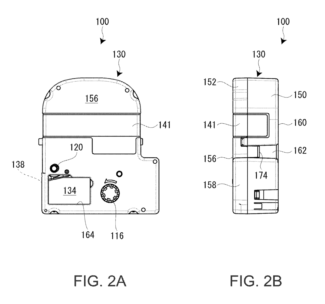
Examples
first embodiment
Details of Detection Portion and Detection Object (First Embodiment)
[0090]Next, a structure around the detection portion 51 of the cartridge mounting portion 5 and a structure around the detection object 180 of the tape cartridge 100 are described in detail with reference to FIGS. 7 to 9. FIG. 7 is a perspective view of the cartridge mounting portion 5, FIG. 8 is a perspective view of the lower case 150 of the tape cartridge 100, and FIG. 9 is an enlarged sectional view of portions around the detection portion 51 and the detection object 180 in a state where the tape cartridge 100 is mounted on the cartridge mounting portion 5.
[0091]As shown in the drawings, the detection portion 51 configured of the plurality of (four in the shown example) conductive contactors 51a (spring pieces) is provided on the positioning protrusion portion 41 (engagement projection portion) of the cartridge mounting portion 5. Meanwhile, the detection object 180 is provided on the inner peripheral portion of...
second embodiment
[0126]Next, as a second embodiment, an embodiment in which the conductive contactors 51a are used as simple spring pieces is described. In the second embodiment, portions different from those of the first embodiment are mainly described. In this embodiment, a tape detection portion (not shown) corresponding to the detection portion 51 is provided in the vicinity of the winding drive shaft 47, and a tape detection object (not shown) corresponding to the detection object 180 is provided on the tape cartridge 100 corresponding to the tape detection portion.
[0127]As shown in FIG. 14A, four spring pieces 401 are provided on the positioning protrusion portion 41, and the four spring pieces 401 come into direct contact with the inner peripheral surface of the core shaft portion 192. Each spring piece 401 has the same shape as that of the conductive contactor 51a, and similarly to the first embodiment, the spring pieces 401 are held by a spring holder 403 corresponding to the insulating hol...
third embodiment
[0135]Next, a third embodiment is described with reference to FIG. 15. In the third embodiment, portions different from those of the second embodiment are mainly described.
[0136]As shown in FIG. 15, in the third embodiment, the positioning protrusion portion 41 (second projection portion 302) and a plurality of (four) spring pieces 401B are integrally formed. That is, the four spring pieces 401B are formed by partially removing the peripheral wall in a “U” shape at four locations of the second projection portion 302 in the peripheral direction. Each spring piece 401B includes a plate-shaped spring portion 431 which is suspended from the shoulder portion of the second projection portion 302, and a hemispherical protrusion 433 which protrudes from the outer surface of the lower end portion of the plate-shaped spring portion 431.
[0137]In this case, if the second recessed portion 322 of the core shaft portion 192 is fitted to the second projection portion 302 of the positioning protrusi...
PUM
 Abstract
Description
Claims
Application Information