Strainer for oil supply mouth

Inactive Publication Date: 2005-05-05
DAIWA SEIKO CORPORATION +1
View PDF3 Cites 4 Cited by
  • Summary
  • Abstract
  • Description
  • Claims
  • Application Information

AI Technical Summary

Benefits of technology

[0008] Paying an attention to these problems, it is an object of the invention to provide a strainer for an oil supply mouth, preventing the oil flowing when supplying from colliding with the float so as to accurately detect the height of the liquid level.
[0024] Depending on the strainer for the oil supply mouth of the invention, when the oil comes to the reference liquid level during supplying the oil, since the flowing of the oil is prevented from colliding with the float for the oil level gauge, the float is made stable, so that the height of the liquid level can be accurately detected. That is, because the float for the oil level gauge is inserted in the guide hole formed to be hollow in the frame composing the strainer body, the float can be smoothly attached to the oil supply mouth, and at the same time, the portions of the guide hole or the float formed in the frame body are avoided from breakage when attaching them or supplying the oil.

Problems solved by technology

By the way, when attaching the strainer to the oil supply mouth, a height of a liquid level within the oil tank cannot be visually recognized from the outside during supplying the oil.
However, in the strainer disclosed in Patent Literature 1, since the float is supported at the inside of the strainer body, there is a problem that when inserting the oil supply hose to supply the oil, the flowing of the oil collide with the float, so that the float spoils stability and fluctuates up and down, and the height of the liquid level cannot be accurately detected.
In the strainer disclosed in Patent Literature 2, the float is supported outside of the strainer, and the oil can be prevented from directly colliding with the float during supplying the oil as Patent Literature 1, but there is a problem that since the circumferential wall of the strainer is formed with the network body, the flowing of the supplying oil passes through the network body and collides with the float (particularly, the spherical floating part exposed outside), and as a result, even when the oil comes up to the reference liquid level, the float loses stability, and the height of the liquid level cannot be accurately detected.

Method used


Image

  • Strainer for oil supply mouth
  • Strainer for oil supply mouth
  • Strainer for oil supply mouth

Examples


first embodiment

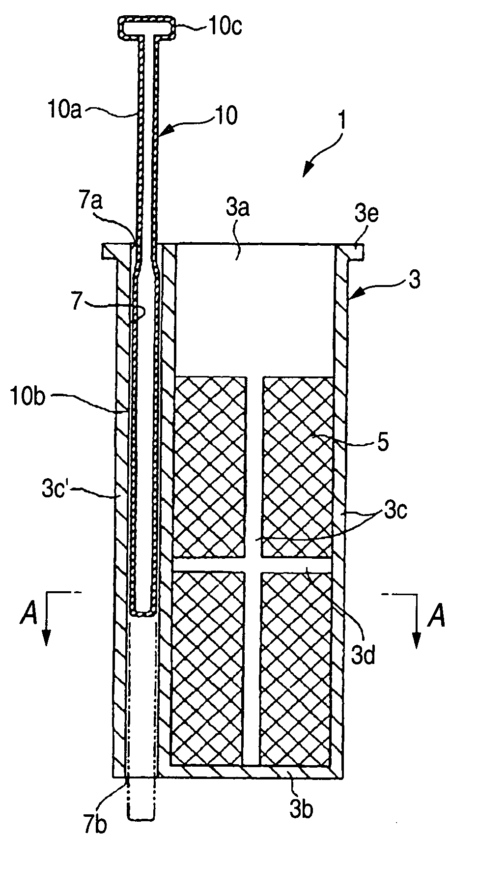
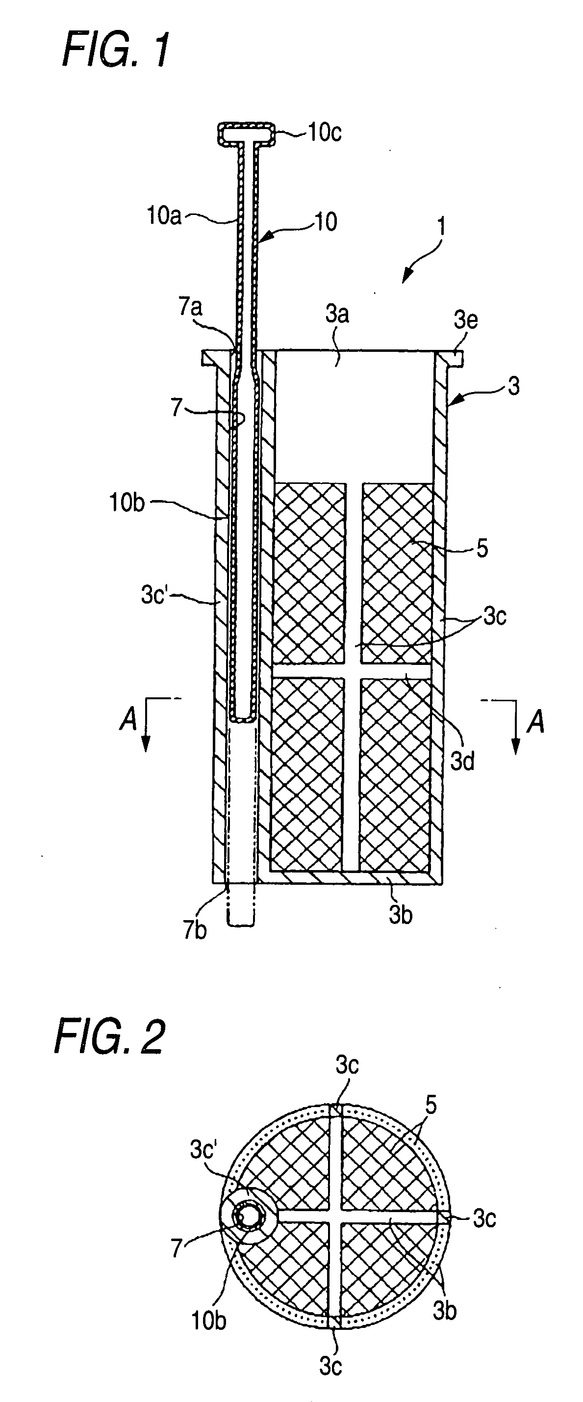
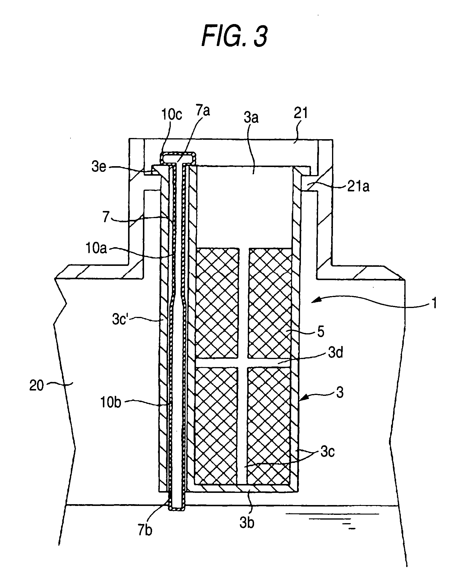
[0043] FIGS. 1 to 5B are views showing the strainer according to the invention, in which FIG. 1 is a vertical cross sectional view of the strainer, FIG. 2 is a plan view along A-A line of FIG. 1, FIG. 3 is a vertical cross sectional view showing the condition of attaching the strainer shown in FIG. 1 to the oil supply mouth, FIG. 4 is a vertical cross sectional view showing the condition where the liquid level of the oil rises (the condition of the reference liquid level) after the strainer is attached to the oil supply mouth, and FIGS. 5A and B show the structural examples of the floats, respectively.

[0044] The strainer body is formed to be cylindrical (almost cup shaped) with a bottom opening upward, and according to the present embodiment, the strainer 1 is formed as a circular cylinder having a bottom corresponding to a diameter of the oil supply mouth 21 of the oil tank 20. The body 1 has a frame body 3 maintaining its inherent rigidity and avoiding breakage, and a net part 5 (...

second embodiment

[0055] FIGS. 6 to 9 are views showing the strainer according to the invention, in which FIG. 6 is a vertical cross sectional view of the strainer, FIG. 7 is a plan view along B-B line of FIG. 6, FIG. 8 is a vertical cross sectional view showing the condition of attaching the strainer shown in FIG. 6 to the oil supply mouth, and FIG. 9 is a vertical cross sectional view showing the condition where the liquid level of the oil rises (the condition of the reference liquid level) after the strainer is attached to the oil supply mouth.

[0056] Similarly to the above mentioned embodiment, of the plural frames composing the frame body 3, one of the vertical frames 3c is formed with a swelling part 3f in a half-pillar shape inside of the strainer body 1, and is here unified as one body with the guide hole 7 being hollow and opening at the upper and lower end. The float 10 for an oil level gauge is inserted movably in the vertical directions into the guide hole 7. In this case, the swelling par...

third embodiment

[0059] FIGS. 10 to 13 are views showing the strainer according to the invention, in which FIG. 10 is a vertical cross sectional view of the strainer, FIG. 11 is a plan view along C-C line of FIG. 10, FIG. 12 is a vertical cross sectional view showing the condition of attaching the strainer shown in FIG. 10 to the oil supply mouth, and FIG. 13 is a vertical cross sectional view showing the condition where the liquid level of the oil rises (the condition of the reference liquid level) after the strainer is attached to the oil supply mouth.

[0060] Similarly to the above mentioned embodiment, of the plural frames composing the frame body 3, one of the vertical frames 3c is formed with a swelling part 3g in a half-pillar shape outside of the strainer body 1, and is here unified as one body with the guide hole 7 being hollow and opening at the upper and lower end. The float 10 for an oil level gauge is inserted movably in the vertical directions into the guide hole 7. The swelling part 3g ...


PUM


Abstract

The invention is an object of the invention to provide a strainer for an oil supply mouth, preventing the oil flowing when supplying the oil from colliding with the float so as to accurately detect the height of the liquid level. The strainer for an oil supply mouth of the invention has a guide hole equipped in vertical directions and a float for an oil level gauge passing movably in vertical directions through this guide hole. When the oil comes up to an at least reference liquid level, the float is received at a lower end within the guide hole.

Description

BACKGROUND OF THE INVENTION [0001] The present invention relates to a strainer to be attached to an oil supply mouth of an oil tank provided to heavy weight machinery such as construction equipment for preventing impurities from entering into the oil tank during supplying an oil, and to a strainer for an oil supply mouth having a float for an oil gauge enabling to detect a position of a liquid level. [0002] In general, the above mentioned strainer for oil supply mouth (called briefly as “strainer” hereafter) is formed to be like a cup and structured by securing network bodies to surround a periphery of a frame, and this is attached as fitted into the oil supply mouth. When attaching the strainer and inserting an oil supply hose, impurities can be caught by the network body. [0003] By the way, when attaching the strainer to the oil supply mouth, a height of a liquid level within the oil tank cannot be visually recognized from the outside during supplying the oil. As disclosed in Pate...

Claims


Application Information

Patent Timeline
IPC IPC(8): B01D35/02B60K15/04B60K15/077F01M11/04F15B1/26G01F23/30G01F23/58
CPCG01F23/58
Inventor YAGI, HIROSHIUTO, RYOJI
Owner DAIWA SEIKO CORPORATION
Why Eureka
Try Eureka