Fastener for fastening a resin component

a technology for fasteners and resin components, applied in the direction of threaded fasteners, mechanical equipment, transportation and packaging, etc., can solve the problems of manufacturing cost, inability to easily employ in terms of improving workability, and time-consuming detachment of bushets, so as to improve workability and reduce manufacturing costs. , the effect of easy us

Inactive Publication Date: 2018-01-25
TOYOTA BOSHOKU KK
View PDF15 Cites 4 Cited by
  • Summary
  • Abstract
  • Description
  • Claims
  • Application Information

AI Technical Summary

Benefits of technology

[0005]In the meantime, the configuration in which the bush is press-fitted into or integrated with the resin component requires a dedicated facility and process and therefore cannot be easily employed in terms of improving the workability, in terms of reducing the manufacturing cost, and so on. Further, when the bush is press-fitted into the insertion hole to strongly interfere with the inner surface of the insertion hole, it takes time to detach the bush, for example, in the maintenance work. Naturally, it is also possible to insert the bush through the insertion hole in a non-press-fitted state without using a special tool, but, in that case, the possibility of coming-off of the bush from the resin component is extremely increased. The disclosure provides a fastener that can be attached to a resin component in such a way as to be detachable more smoothly while coming-off of the fastener from the resin component is prevented as much as possible.
[0006]According to an aspect of the disclosure, a fastener for fastening a resin component, the fastener configured to be interposed between an insertion hole provided in the resin component and a fastening member inserted through the insertion hole, includes: an insertion portion having a tubular shape and insertable through the insertion hole in a non-press-fitted state; a flange portion protruding radially outward of the insertion portion from an end portion of the fastener; and a recessed portion provided on an outer surface of the insertion portion. In the state where the insertion portion is inserted through the insertion hole, the flange portion is disposed outside the insertion hole, and a projecting portion protruding from an inner surface of the insertion hole is disposed in the recessed portion of the insertion portion. In this type of configuration, it is desirable that the fastener be attached to the resin component in such a way as to be detachable more smoothly while preventing coming-off of the fastener from the resin component as much as possible. In this aspect, since the tubular insertion portion is inserted through the insertion hole in the non-press-fitted state, it is possible to smoothly attach and detach the fastener to and from the resin component. The pressure from, for example, a bolt member as the fastening member is received by the flange portion disposed outside the insertion hole, and the projecting portion protruding from the inner surface of the insertion hole is disposed in the recessed portion of the insertion portion. Therefore, while fulfilling the function as the fastener, it is also possible to suitably restrict the movement of the insertion portion in a coming-off direction with respect to the insertion hole by interference between the projecting portion and the recessed portion.
[0007]In the above-described aspect, the depth from an opening of the recessed portion to its bottom may be greater than the projecting portion. In this configuration, by setting the depth from the opening of the recessed portion to its bottom to be greater than the projecting portion, smooth relative movement of the fastener is made possible.
[0008]In the above-described aspect, the fastener may be a nut for the fastening member. In the above-described aspect, the insertion portion may include an abutting portion formed by cutting out the outer surface of the insertion portion into a flat surface. In this configuration, the abutting portion of the insertion portion abuts against a rotation preventing portion of the insertion hole to restrict the rotational motion of the fastener, so that the fastener can be suitably used as the nut.
[0009]According to the above-described aspect, the fastener can be attached to the resin component in such a way as to be detachable more smoothly while coming-off of the fastener from the resin component is prevented as much as possible.

Problems solved by technology

In the meantime, the configuration in which the bush is press-fitted into or integrated with the resin component requires a dedicated facility and process and therefore cannot be easily employed in terms of improving the workability, in terms of reducing the manufacturing cost, and so on.
Further, when the bush is press-fitted into the insertion hole to strongly interfere with the inner surface of the insertion hole, it takes time to detach the bush, for example, in the maintenance work.

Method used


Image

  • Fastener for fastening a resin component
  • Fastener for fastening a resin component
  • Fastener for fastening a resin component

Examples


example 2

[0063]In Example 2, for those members having substantially the same basic configurations as the constituent members of Example 1, a detailed description thereof will be omitted by assigning corresponding reference symbols thereto or the like. Referring to FIG. 11, Example 2 differs from Example 1 in that an upper insertion hole 40H in the form of an elongated hole is provided in a middle fastening seat 40. The upper insertion hole 40H is an arc-shaped elongated hole that is elongated in the right-left direction and is gradually curved forward as approaching its right and left ends. Further, projecting portions 45a are respectively provided at the front upper edge and the rear upper edge of the upper insertion hole 40H, and each extend in the right-left direction along the corresponding upper edge. In this Example, a fastener 50 inserted through the upper insertion hole 40H can be relatively moved relatively largely in a longitudinal direction D3 of the upper insertion hole 40H. Ther...

example 3

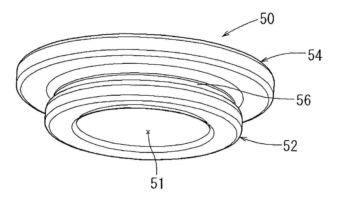
[0064]In Example 3, for those members having substantially the same basic configurations as the constituent members of Example 1, a detailed description thereof will be omitted by assigning corresponding reference symbols thereto or the like. Referring to FIGS. 12 to 15, Example 3 differs from Example 1 in that a fastener 90 is a member that serves as a nut, and in that there is provided a configuration for preventing the rotation of the fastener 90 with respect to an upper insertion hole 43H of a middle fastening seat 43. Referring to FIG. 12, the fastener 90 of this Example includes an insertion hole portion 91, an insertion portion 92, a flange portion 94 having the same configuration as in Example 1, and a pair of recessed portions 96. While the insertion hole portion 91 has substantially the same configuration as in Example 1, the insertion hole portion 91 is provided on its inner surface with a screw groove that can be screwed on a shaft portion 60b of a bolt member 60 shown i...


PUM


Abstract

Provided is a fastener for fastening a resin component. The fastener is interposed between an insertion hole provided in the resin component and a fastening member inserted through the insertion hole. The fastener includes: an insertion portion having a tubular shape and insertable through the insertion hole in a non-press-fitted state; a flange portion protruding radially outward of the insertion portion from an end portion of the fastener; and a recessed portion provided on an outer surface of the insertion portion. In the state where the insertion portion is inserted through the insertion hole, the flange portion is disposed outside the insertion hole, and a projecting portion protruding from an inner surface of the insertion hole is disposed in the recessed portion of the insertion portion.

Description

INCORPORATION BY REFERENCE[0001]The disclosure of Japanese Patent Application No. 2016-145585 filed on Jul. 25, 2016 including the specification, drawings and abstract is incorporated herein by reference in its entirety.BACKGROUND1. Technical Field[0002]The disclosure relates to a fastener for fastening a resin component, and more specifically relates to a fastener that is interposed between an insertion hole provided in a resin component and a fastening member such as a bolt member.2. Description of Related Art[0003]A bush as this type of fastener that is used for fastening between resin component and a metal component has a moderate hardness and includes a tubular insertion portion and a disc-shaped flange portion. When fastening the resin component and the metal component to each other, a bolt member as a fastening member is inserted through an insertion hole of the resin component via the bush and screwed into a nut on the metal component side so as to be fixed. In this event, t...

Claims


Application Information

Patent Timeline
Patent Type & Authority Applications(United States)
IPC IPC(8): F16B19/10F16B2/24F16B13/02F16F1/373
CPCF16B19/10F16F1/3732F16B1/00F16B13/02F16B2/24B60N2/682F16B5/0225F16B21/073F16B37/043
Inventor MATSUSHIMA, IWAO
Owner TOYOTA BOSHOKU KK
Why Eureka
Try Eureka