Tensioner lever

a technology of tensioner lever and tensioner body, which is applied in the direction of belt/chain/gearring, mechanical equipment, and mechanical components, etc., can solve the problems of tensioner lever deformation, deformation of the lever body itself as the tensioner lever ages, and deformation of the stopper pin lock hole, etc., to achieve suppressed chain bouncing, simple configuration, and high spring load

Active Publication Date: 2022-09-06
TSUBAKIMOTO CHAIN CO
View PDF17 Cites 4 Cited by
  • Summary
  • Abstract
  • Description
  • Claims
  • Application Information

AI Technical Summary

Benefits of technology

[0007]The present invention solves this problem and it is an object of the invention to provide a tensioner lever that can reduce vibration and noise when the chain runs, and realize smooth attachment into an engine with minimal deformation of the lever body with a simple configuration.
[0009]According to the tensioner lever set forth in claim 1, the load applied to the lever body by the torsion coil spring in a state in which the support arm is locked by the stopper member can be reduced, and therefore deformation such as twisting of the lever body resulting from the spring load can be prevented. This allows for smooth assembling of the tensioner lever to the engine, and enables the tensioner lever to exhibit its designed performance consistently. This in turn enables use of a torsion coil spring with a higher spring load, whereby correct reaction force can be exerted to tension fluctuations that accompany changes in chain behavior, and bouncing of the chain can be suppressed.
[0010]Moreover, expected effects can be achieved with a simple configuration without compromising the characteristic advantages of tensioner levers such as better fuel economy by the non-use of hydraulic pressure, and better fuel economy by the small and light weight design.
[0011]The configuration set forth in claim. 2 helps to further reduce the load applied to the lever body in a state in which the support arm is locked by the stopper member, which reliably prevents deformation of the lever body, and allows for smooth assembling work of installing the torsion coil spring and attaching the tensioner lever to the attachment surface.
[0012]The configuration set forth in claim 3 prevents unintended release of the engagement between the support arm and the stopper member.

Problems solved by technology

It has been discovered that, a torsion coil spring with a high spring load, if applied to tensioner levers of Japanese Patent Application Laid-open Nos. 2009-108909, 2016-160985, and 2017-115952, could cause deformation of the stopper pin lock hole, or deformation of the lever body itself as the tensioner lever ages.
Such a deformation could lead to various problems such as assembling failure of the tensioner lever, shoe surface skewing, or defects in the chain line that is the running track of the chain.

Method used


Image

  • Tensioner lever
  • Tensioner lever
  • Tensioner lever

Examples


Embodiment Construction

[0020]A tensioner lever that is one embodiment of the present invention will be hereinafter described with reference to the drawings.

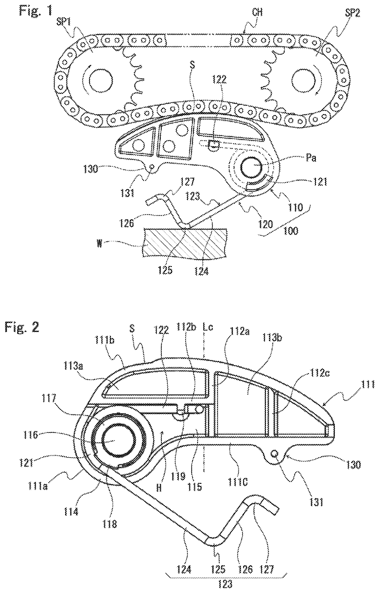
[0021]The tensioner lever 100, as shown in FIG. 1, is pivotably mounted on a pivot shaft Pa protruding from an attachment surface (not shown) of an engine block (not shown) or the like to slidably guide a chain CH passed over between a drive-side sprocket SP1 attached to a crankshaft and a driven-side sprocket SP2 attached to a shaft of an auxiliary machine to keep an appropriate chain tension.

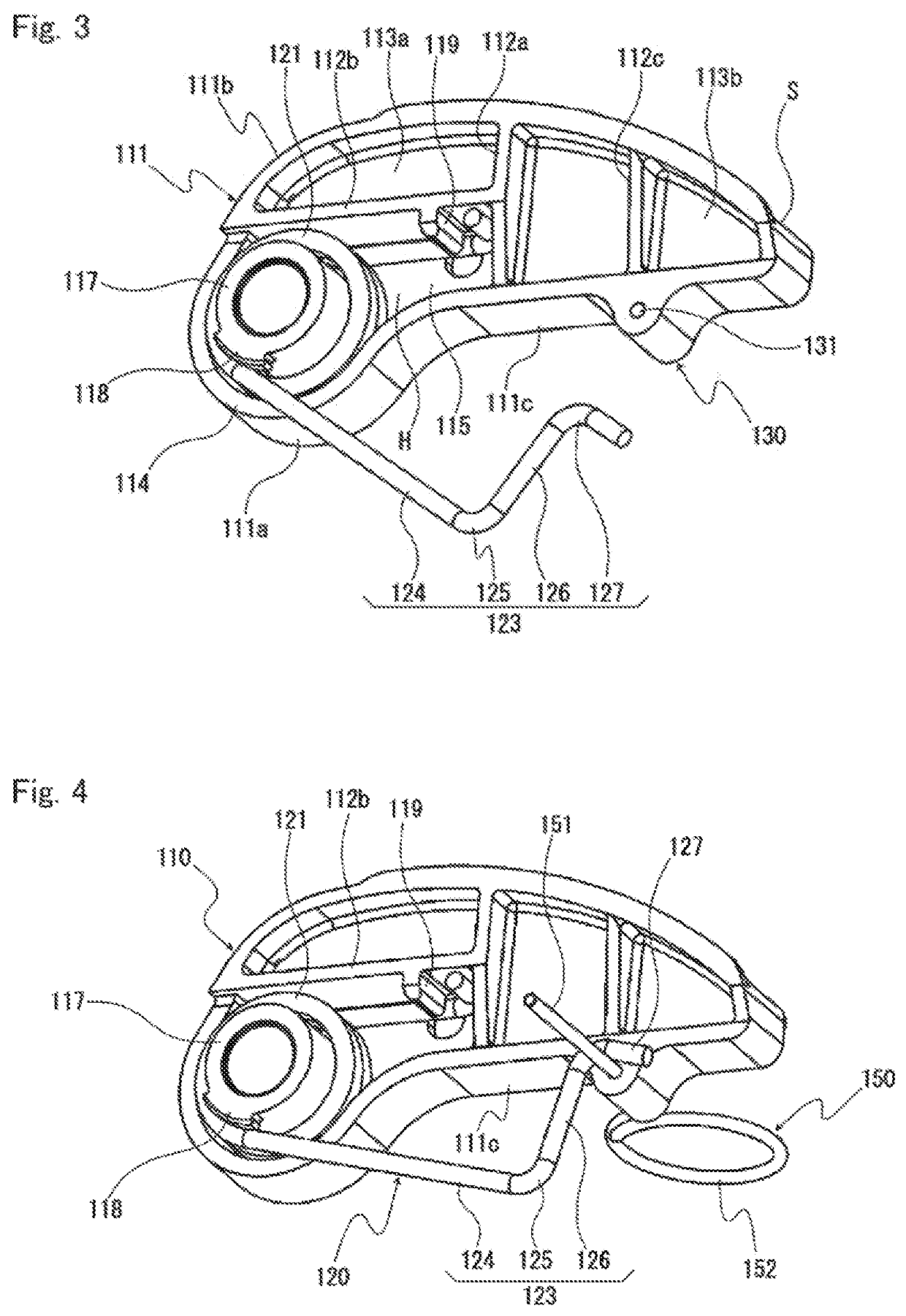
[0022]The tensioner lever 100 includes a lever body 110 having a shoe surface S formed along a longitudinal direction for slidably guiding the chain CH and a base end rotatably supported on an attachment surface, and a torsion coil spring 120 interposed between the lever body 110 and the attachment surface to press the shoe surface S toward the chain CH. As illustrated in FIG. 1, the resilient force of the torsion coil spring 120 exerts a torque on the lever body...


PUM


Abstract

An object of the present invention is to provide a tensioner lever that can reduce vibration and noise when the chain runs, and realize smooth attachment into an engine with minimal deformation of the lever body with a simple configuration. A tensioner lever according to the present invention includes a lever body and a torsion coil spring pressed the lever body toward the chain. The lever body includes a stopper member mounting part where a stopper member by which the support arm of the torsion coil spring is locked and which retains the torsion coil spring in a compressed state is removably mounted. The stopper member mounting part is located closer to a distal end of the lever body than a center position in the longitudinal direction of the lever body, or a center of gravity position of the lever body.

Description

BACKGROUND OF THE INVENTION1. Field of the Invention[0001]The present invention relates to a tensioner lever that slidably guides a running chain, and more particularly to a chain tensioner lever that slidably guides a chain by pressing a shoe surface of a lever body against the chain by the resilient force of a torsion coil spring.2. Description of the Related Art[0002]Tensioner levers have been used in chain transmissions for an auxiliary machine or the like of a car engine to remove slackness in chains and to prevent vibration of running chains. One such known tensioner lever, which is pivotably attached to an attachment surface of an engine block or the like, includes a lever body having a shoe surface that slidably guides the chain, and a torsion coil spring interposed between the lever body and the attachment surface to press the shoe surface toward the chain (see, for example, Japanese Patent Application Laid-open Nos. 2009-108909, 2016-160985, and 2017-115952).[0003]These te...

Claims


Application Information

Patent Timeline
Patent Type & Authority Patents(United States)
IPC IPC(8): F16H7/08F16H7/18
CPCF16H7/08F16H7/18F16H2007/081F16H2007/0846F16H2007/0872F16H2007/0878F16H2007/0893F16H2007/185F16H2007/0842F16H2007/0897
Inventor WATANABE, MASANORIHAMAGUCHI, SHUJI
Owner TSUBAKIMOTO CHAIN CO
Why Eureka
Try Eureka