

Systems and methods for reduced crimp carbon fiber helical fabric
a technology of helical fiber and carbon fiber, which is applied in the direction of weaving, ornamental textile articles, looms, etc., can solve the problems of large amount of fiber waste, large amount of fiber selection and fiber architecture design limitations, and performs subsequently subject to a costly carbonization cycle to transform the fibers, so as to reduce the load of primary fibers, reduce the cross section, and reduce the effect of crimp fabrics
Active Publication Date: 2013-09-05
THE BF GOODRICH CO
View PDF8 Cites 12 Cited by
- Summary
- Abstract
- Description
- Claims
- Application Information
AI Technical Summary
Benefits of technology
This patent describes a way to make fabrics with minimum crimp, which can be used to make annular preforms for aerospace applications. The fabrics are made by weaving carbon fibers with interlocking yarns, which are small and help to maintain the fiber structure in place during the weaving process. This results in low crimp and ensures that the fabrics can be used without additional steps to reduce crimp, such as burning. Overall, this patent provides a way to make high-quality, near net shape panels for use in aerospace applications.
Problems solved by technology
The preforms are subsequently subjected to a costly carbonization cycle to transform the fibers into carbon.
This approach yields a large amount of fiber waste and has limitations in fiber selection and fiber architecture designs.
Weaving typically yields fabrics with undesired fiber crimp levels in both warp and weft directions, especially in a weave pattern such as plain weave.
The crimp present in the starting fabric degrades the in plane mechanical and thermal properties of the finished carbon carbon composite.
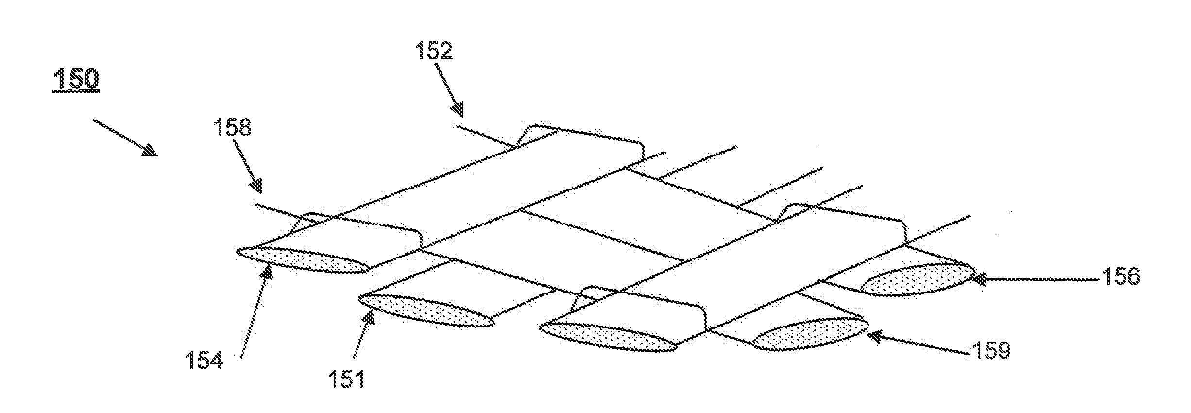
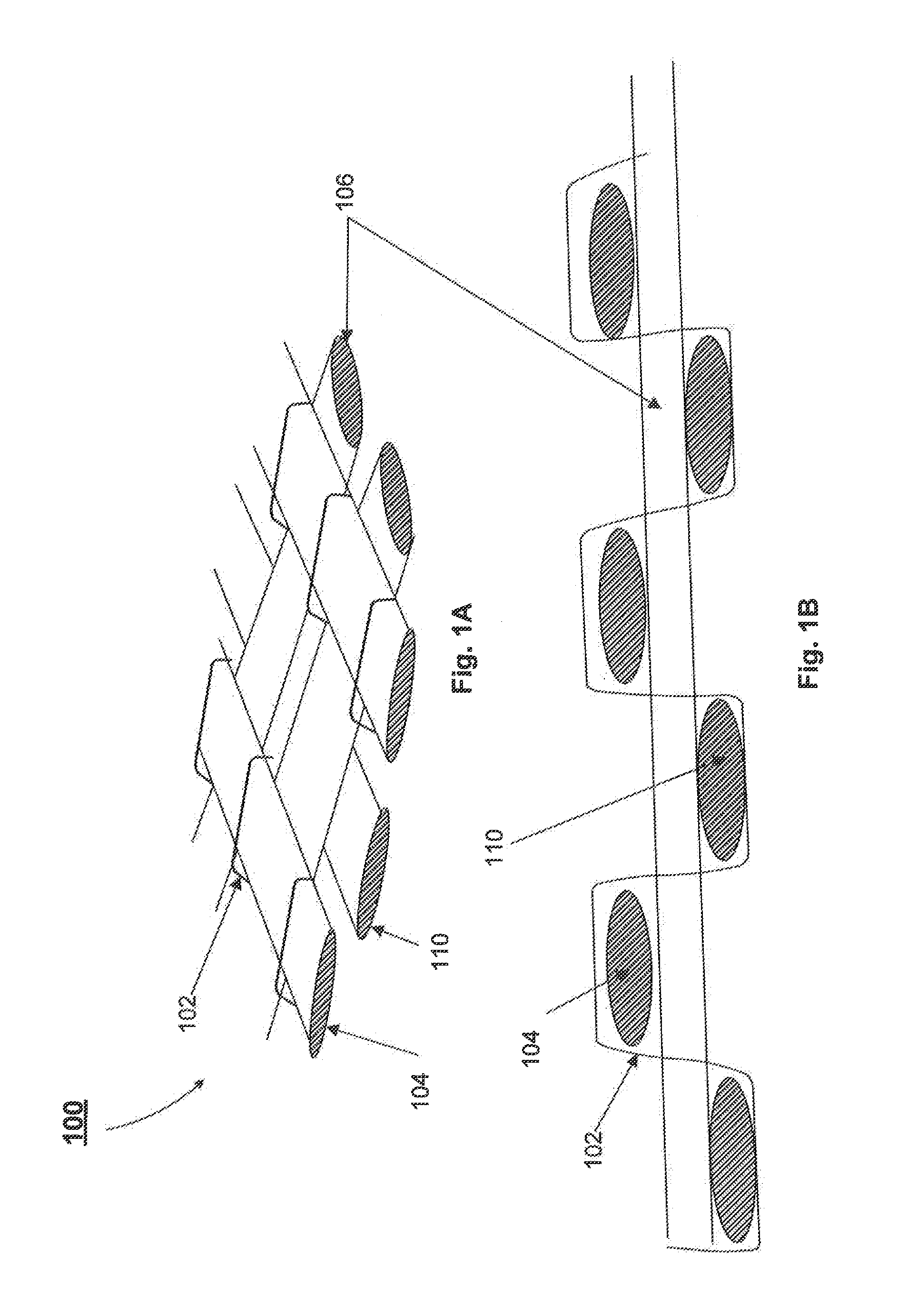
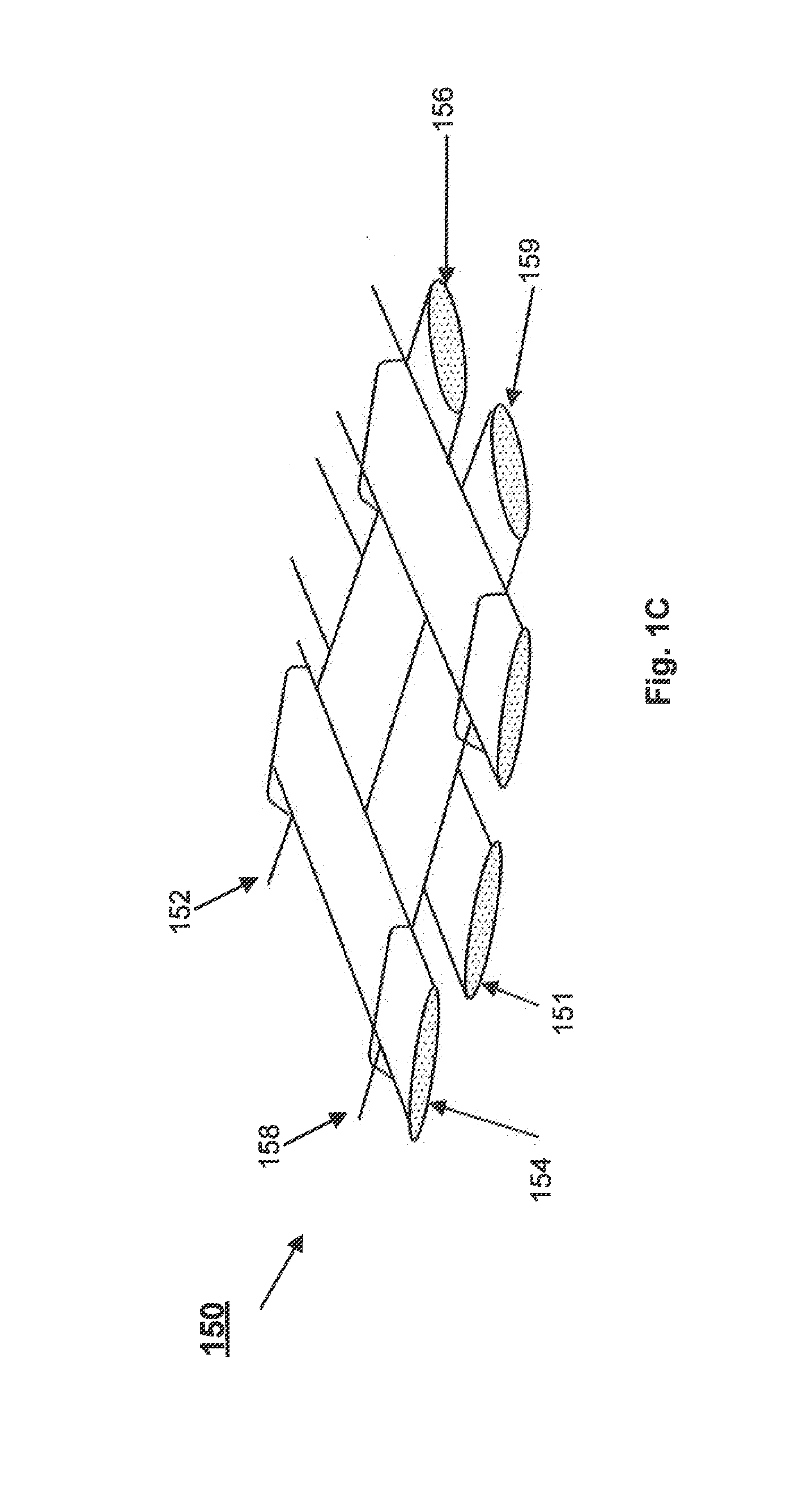
Specific weave constructions combined with the use of small tex yarns to maintain the fiber architecture in place may tend to result in low crimp well and warp carbon fibers.
Method used
View moreImage
Smart ImageViewing Examples

Examples
example
[0042]One high areal weight helical carbon fabric showing no evidence of fiber crimp was fabricated with the proposed invention. The 1400 g / m2 fabric was prepared with a plain weave pattern alternating every other primary warp carbon fiber tow with a cotton yarn. The warp carbon fiber was a 48K tow and the interlocking yarn was a 40 denier cotton yarn. The fabric handled very well during packaging steps and feeding into a circular needle-punch loom where several near net shape preforms were fabricated.
Login to View More PUM
| Property | Measurement | Unit |
|---|---|---|
| temperatures | aaaaa | aaaaa |
| temperatures | aaaaa | aaaaa |
| temperatures | aaaaa | aaaaa |
Abstract
Systems and methods for weaving helical carbon fabrics with minimum fiber crimp are provided herein. In various embodiments, small denier natural or synthetic yarns are used in the warp direction to interlace the carbon fiber wefts with minimum deformation. Specific weave designs are used in combination with the small denier yarn to maintain the primary carbon fiber weft and warp un-crimped.
Description
FIELD OF INVENTION[0001]This disclosure is generally related to methods, apparatus and manufacturing associated with reduced crimp woven fabrics and, in particular, helical carbon fiber woven fabric.BACKGROUND OF THE INVENTION[0002]Carbon / carbon (“C / C”) parts are employed in various industries. C / C parts may be used as, for example, friction disks such as aircraft brake disks, race car brake disks, clutch disks, and the like. C / C brake disks are especially useful in such applications because of the superior high temperature characteristics of C / C material. In particular, the C / C material used in CC parts is a good conductor of heat, and thus is able to dissipate heat away from the braking surfaces that is generated in response to braking. C / C material is also highly resistant to heat damage, and is capable of sustaining friction between brake surfaces during severe braking, without a significant reduction in the friction coefficient or mechanical failure. Ceramic Matrix Composites (...
Claims
Login to View More Application Information
Patent Timeline
 Patent Type & AuthorityApplications(United States)
IPC IPC(8): D03D15/00D03D41/00D03D15/68
CPCD03D3/08D10B2505/02D03D15/06D03D49/20D10B2101/12D10B2201/02D10B2201/04D10B2201/20D10B2211/02D10B2211/04D10B2321/022D10B2321/10D10B2331/02D10B2331/04D10B2401/063D10B2403/02412D03D15/0094Y10T442/322Y10T442/3252Y10T442/3244D03D15/43D03D15/68
InventorLECOSTAOUEC, JEAN-FRANCOISPEREA, PAUL
OwnerTHE BF GOODRICH CO