Horizontal scrubber system

a scrubber system and horizontal technology, applied in the direction of sulfur compounds, separation processes, alkali metal sulfides/polysulfides, etc., can solve the problem of significant flue gas pressure drop

Inactive Publication Date: 2002-08-15
URS
View PDF2 Cites 48 Cited by
  • Summary
  • Abstract
  • Description
  • Claims
  • Application Information

AI Technical Summary

Benefits of technology

0007] Briefly, and in accordance with the present invention, a scrubber system is provided which enables a substantially horizontal flow path for t...

Problems solved by technology

Other absorber designs also result in a significant flue g...

Method used


Image

  • Horizontal scrubber system
  • Horizontal scrubber system
  • Horizontal scrubber system

Examples


Embodiment Construction

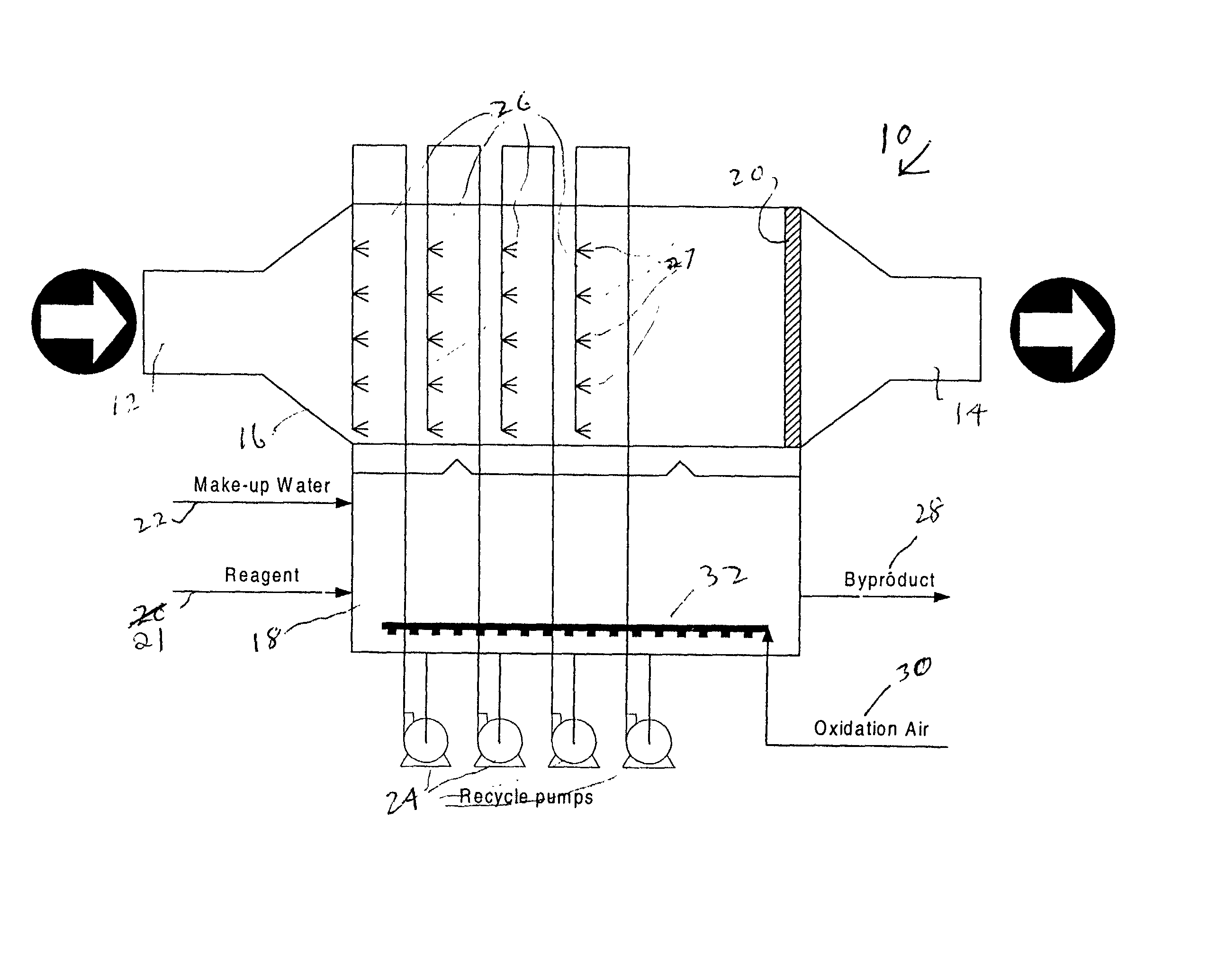
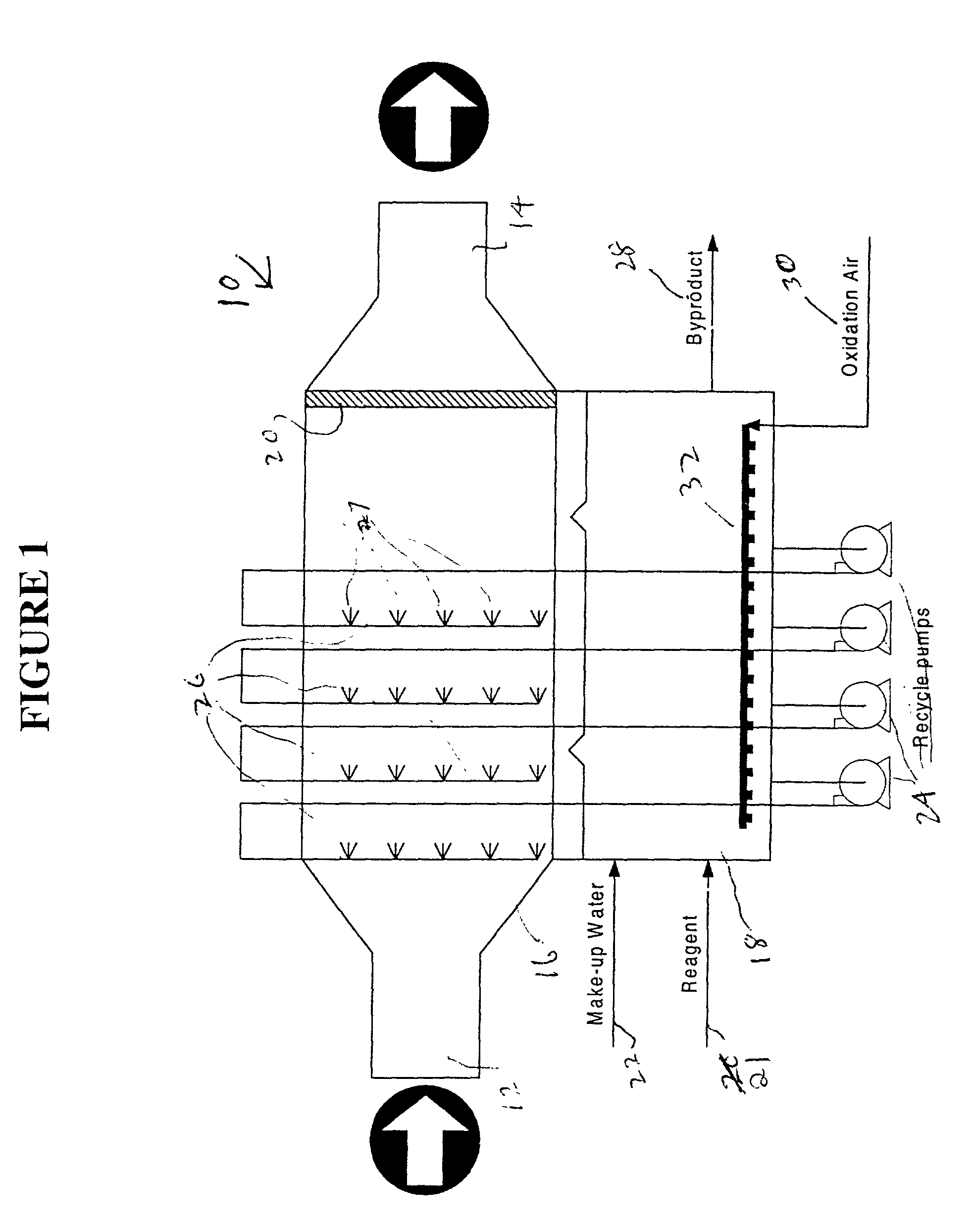
[0016] The general features of the scrubbing systems of the present invention are illustrated in FIG. 1. The system 10 shown therein is characterized by several new and innovative features. A major such feature is the horizontal gas path which makes the scrubber very compact and provides a very low profile. The gas paths leading into the scrubber and leaving from the scrubber are very simple and can connect to an upstream particulate control device or possible booster fan without complicated duct runs. Similarly, the outlet duct can be connected through a straight duct run with the stack.

[0017] The gas velocity at the inlet 12 to and exit 14 from the scrubber will typically be in the range of 50 to 60 fps. The velocity inside the scrubber will typically be between 20 to 30 fps.

[0018] The scrubber spray zone 16 is integrally connected to the reaction tank 18. Spray introduced into the scrubber path will fall by gravity into the reaction tank. The reaction tank 18 spans the entire gas...


PUM

PropertyMeasurementUnit
Temperatureaaaaaaaaaa
Pressureaaaaaaaaaa
Flow rateaaaaaaaaaa

Abstract

A scrubber system is provided which enables a substantially horizontal flow path for the gas which is being subjected to scrubbing. Among other advantages, this permits operation of the absorber with a differential pressure of zero or less. Scrubber composition spray means are positioned in the horizontal gas flow path for spraying an aqueous scrubber composition in a direction which is generally cocurrent with said gas flow. The system is free of means which spray the scrubber composition in directions countercurrent to said gas flow.

Description

[0001] This application claims priority from Applicant's provisional patent application, filed Nov. 2, 2000 under Serial No. 60 / 245,305.[0002] This invention relates generally to apparatus for desulfurization of flue gases, and more specifically relates to an improved scrubber system which enables effective use of a horizontally oriented gas flow path for the gas being treated in the apparatus. The system characteristics are such as to permit operation of the absorber with a differential pressure drop of zero or less.DESCRIPTION OF PRIOR ART[0003] Air pollution is a very serious and urgent international problem. The sources of air pollution are primarily the products of combustion and are numerous and widespread. Many of the air pollutants are in the form of sulfur-bearing flue gases discharged by fossil-fuel-burning electrical power generating plants or other industries. While the precise impact of these pollutants on the environment is still a subject of some speculation, evidence...

Claims


Application Information

Patent Timeline
IPC IPC(8): B01D53/18
CPCB01D53/18
Inventor KLINGSPOR, JONASCOLLEY, DAVIDGRAY, STERLINGBROWN, GREGLOWELL, PHIL
Owner URS
Why Eureka
Try Eureka