Flare fitting assembly with metal-to-metal line seal

a technology of metal-to-metal line sealing and fitting assembly, which is applied in the direction of fluid pressure sealing joints, hose connections, pipe joints, etc., can solve the problems of hard materials not yielding or deforming, the sealing area can only be relatively low, and the surface seal cannot provide the necessary sealing conta

Inactive Publication Date: 2004-05-04
VISTEON GLOBAL TECH INC
View PDF28 Cites 14 Cited by
  • Summary
  • Abstract
  • Description
  • Claims
  • Application Information

AI Technical Summary

Benefits of technology

As the two coupling members 12 and 34 are threadably engaged, the outwardly flared end 38 of the second coupling member 34 rests on the back side of the flared tube end 32 and draws the flared end 32 inward to contact the arcuate mating surface 22 of the first coupling member 12. As the flared end 32 of tube 30 sealingly engages the arcuate mating surface 22, a circular line seal is formed. The metal tube 30 is of a hard material (i.e., stainless steel) and has minimal deformation as it is pressed onto the arcuate mating surface 22. In this manner, as torque is applied to the coupling members 12 and 34, the line seal which is formed in a circular course radially about the arcuate surface is maintained and the tube material at 32 does not distort to the point of completely conforming itself to the shape of the arcuate mating surface 22. The line seal formed between the arcuate surface 22 and the flared tube end 32 is capable of sustaining high system stress and maintaining high system pressures.
Finally, the engagement end of the second coupling member 34 has a shoulder recess 17 machined into it so as to form a pocket or cavity 26 at the base of the main bore 20 of the first coupling member 12 when the coupling members 12 and 34 are assembled. This prevents the engagement end of the second coupling member 34 from bottoming in the main bore 20 of the first coupling member 12 and reducing or removing the sealing pressure that is applied to the line seal, which would disrupt or degrade the seal.

Problems solved by technology

Although the fitting works well with soft tube materials, the wide sealing area can withstand only relatively low system stress translating to lower pressure applications.
When system applications require either harder materials to be employed, such as stainless steel, or higher system operating pressures to be reached, the standard flare fitting with a flare to conical surface seal cannot provide the necessary sealing contact.
First, the harder materials do not yield or deform to the extent necessary to obtain a good wide contact seal.
Even if an initial wide area contact seal is achieved by use of the standard flare fitting, high pressures will cause leakage.
Secondly, if soft metal tube materials are used for high-pressure applications, additional torque must be applied to the fitting in an attempt to avoid leaks.
This additional torque applied to the coupling members can cause negative results.

Method used


Image

  • Flare fitting assembly with metal-to-metal line seal
  • Flare fitting assembly with metal-to-metal line seal
  • Flare fitting assembly with metal-to-metal line seal

Examples


Embodiment Construction

)

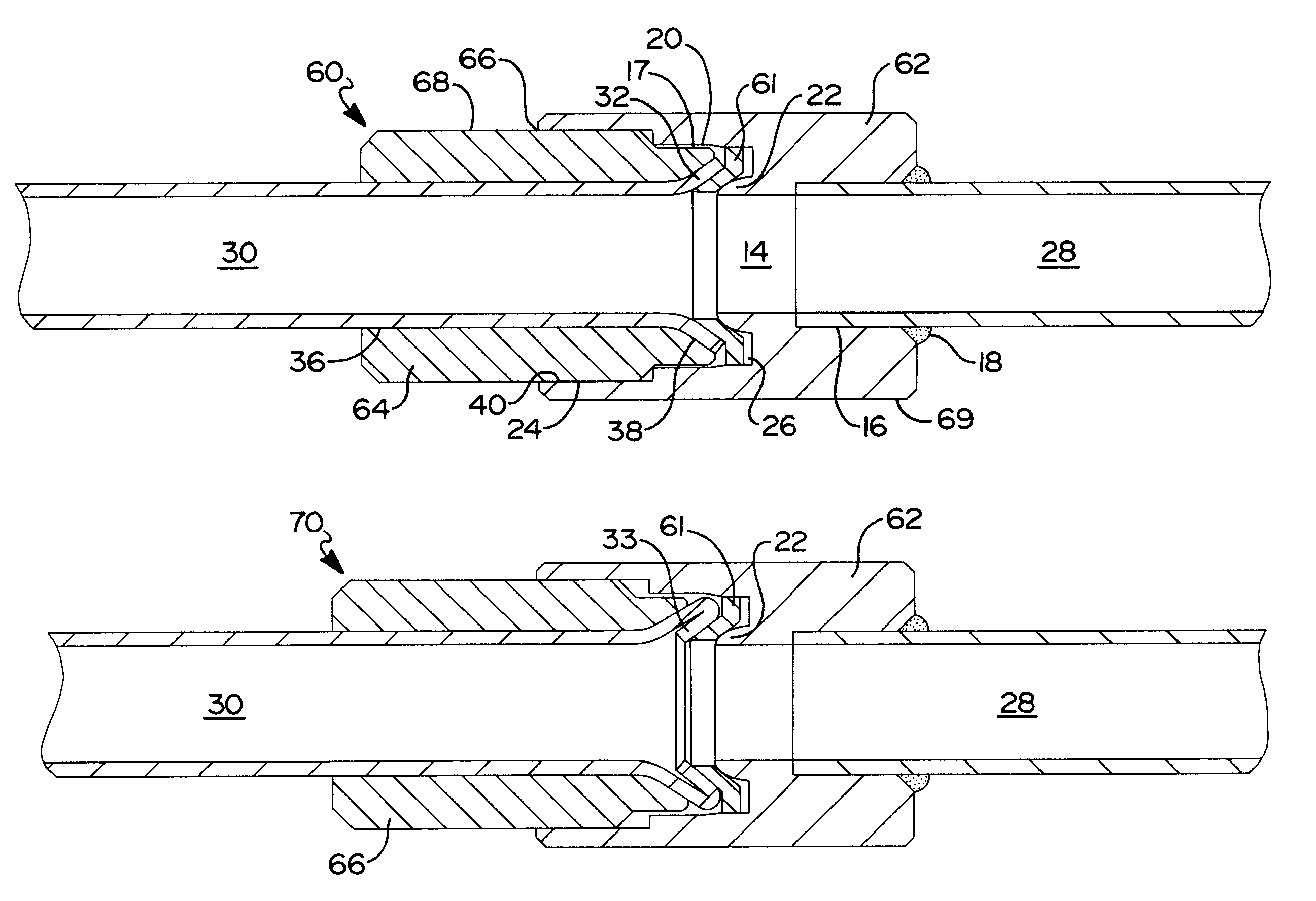
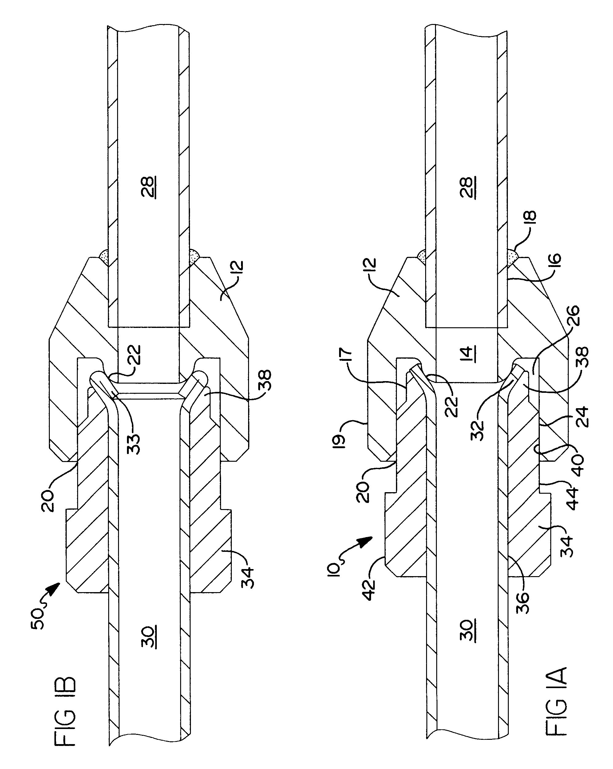
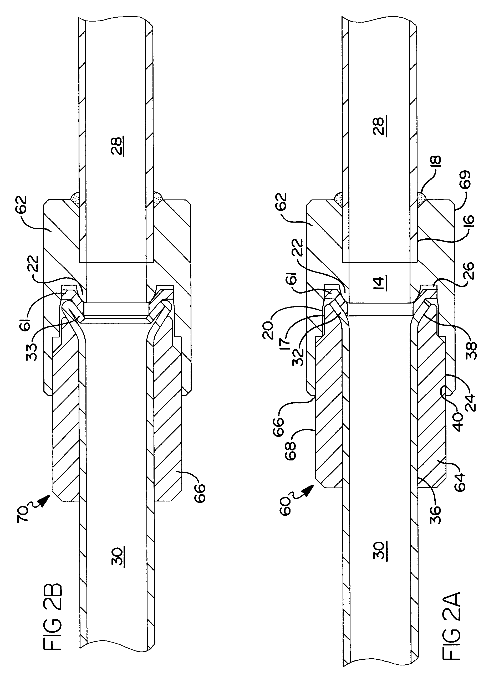
Referring to the drawings and in particular to FIG. 1A, one embodiment of a flare fitting assembly 10, according to the present invention, for coupling of a first metal tube 28 to a second metal tube 30 is shown. The flare fitting assembly 10, in this non-limiting embodiment, may be used in an air conditioning system (not shown) of a motor vehicle (not shown). The flare fitting assembly 10 serves as a tube coupling for the transfer of liquids and / or gasses as required by the system in which it operates and is capable of supporting high-pressure applications.

The flare fitting assembly 10 comprises two coupling members 12 and 34. The first coupling member 12 is generally cylindrical in shape and has a smooth through-bore 14 extending axially with a tube bore 16 at one end and a main bore 20 at the other end. The tube bore 16 is machined such that it can accept the outer diameter of metal tube 28 in a close-tolerance fit. The end of tube 28 is disposed within the tube bore 16 of the f...


PUM


Abstract

A flare fitting assembly includes a first coupling member and a second coupling member adapted to be cooperatively coupled together. The first coupling member has a first through bore with one end adapted to accept and retain a first tube. The second coupling member has a second through bore adapted to be disposed upon a second tube with an outwardly flared end. An arcuately shaped seating surface is disposed within the first through bore of the first coupling member. A conically flared seating surface is disposed within the second through bore of the second coupling member adapted to engage an outer surface of the flared end of the second tube such that a line seal is formed between the inner surface of the flared end of the second tube and the arcuate surface when the first and second coupling members are cooperatively coupled.

Description

1. Field of the InventionThe present invention relates generally to flare fittings and, more specifically, to a flare fitting assembly that interconnects two metal tubes and creates a metal-to-metal line seal used for the transport of pressurized liquids or gasses.2. Description of the Related ArtIt is known to provide a coupling or fitting, for joining a flared tube end to another tube for the transport of pressurized liquids or gasses such as in an air conditioning system of a motor vehicle. Typically, a flare fitting utilizes two coupling members. One of the tube ends to be joined is inserted through a first coupling member and is mechanically flared. The two coupling members of the fitting are engaged together and tightened thereby internally clamping the flared tube end to a conically shaped flare seat, or mating surface within the second coupling member. The practice includes forming the flare with essentially the same angular deflection as the conical seat of the opposing cou...

Claims


Application Information

Patent Timeline
Patent Type & Authority Patents(United States)
IPC IPC(8): F16L19/02F16L19/028
CPCF16L19/0283
Inventor SCHROEDER, FRED GEORGZENG, ZHONGPING
Owner VISTEON GLOBAL TECH INC
Why Eureka
Try Eureka