Sun tracking system for a solar panel

a solar panel and solar energy technology, applied in the field of solar energy tracking system, can solve the problem of increasing the light intensity of the environment of the photo sensor b>101/b> a little more than

Inactive Publication Date: 2009-03-05
LIN JEFFREY +2
View PDF5 Cites 43 Cited by
  • Summary
  • Abstract
  • Description
  • Claims
  • Application Information

AI Technical Summary

Problems solved by technology

The drawback of the prior art as shown in FIG. 1 is that the environmental light intensity o

Method used


Image

  • Sun tracking system for a solar panel
  • Sun tracking system for a solar panel
  • Sun tracking system for a solar panel

Examples


first embodiment

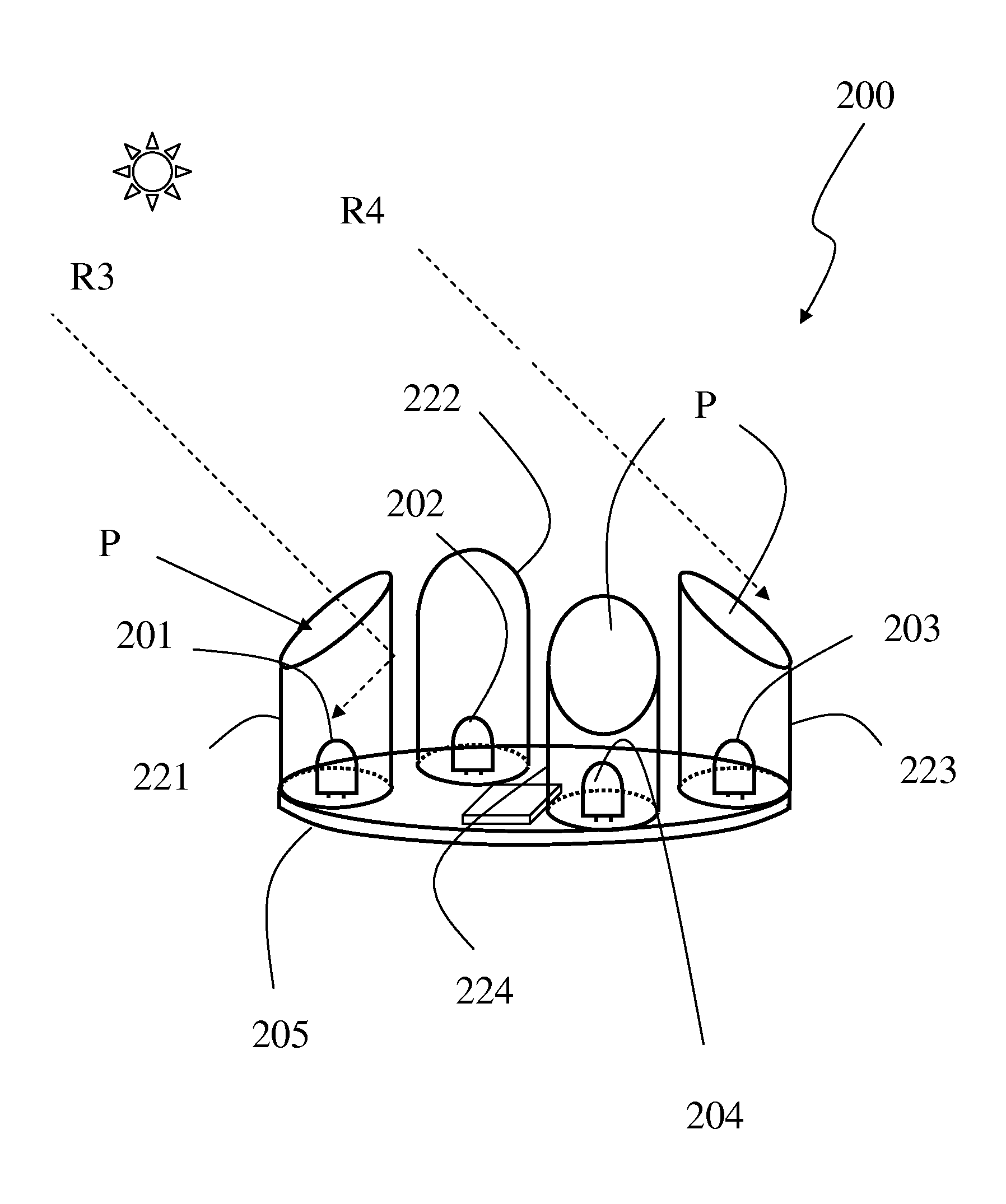
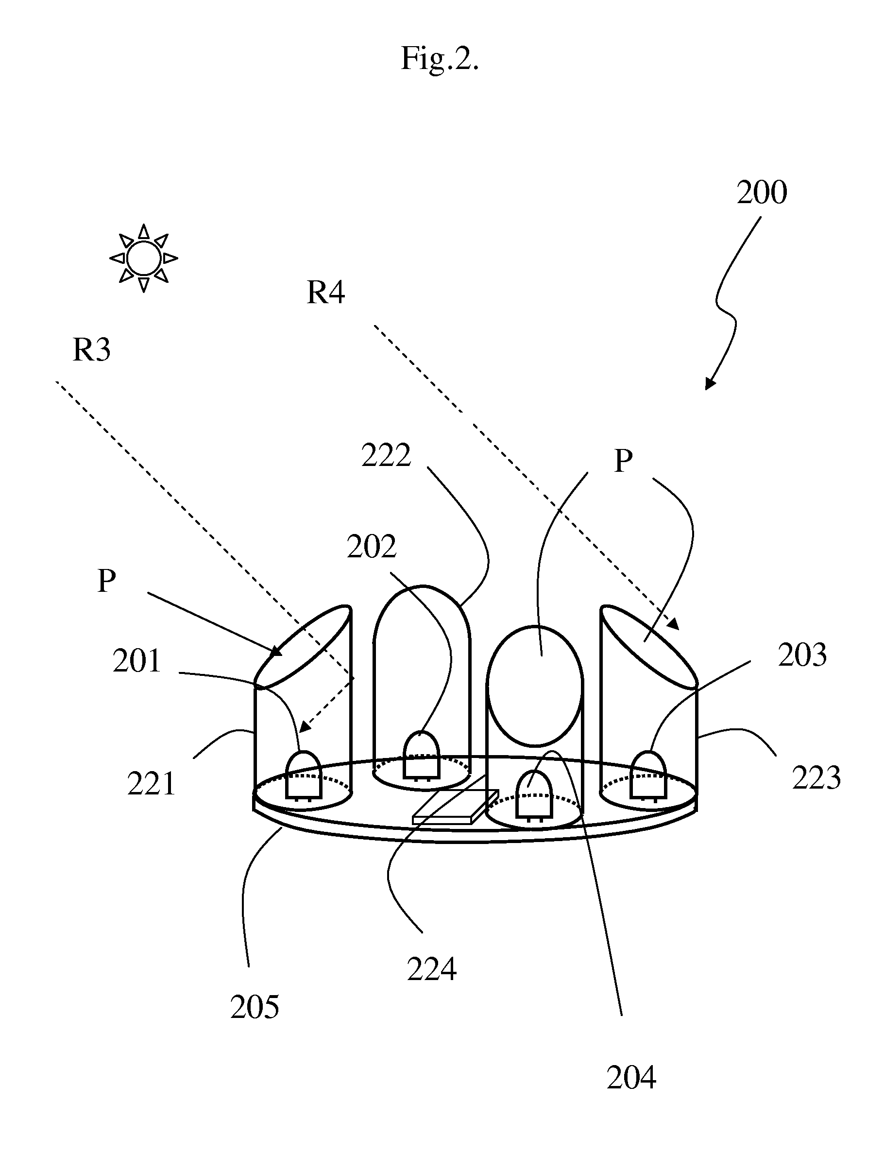
[0012]FIG. 2 shows this invention.

[0013]A sun tracking system 200 mounted on a solar panel 205. A plurality of photo-electricity conversion devices 108 are mounted on the solar panel for collecting and converting solar energy into electricity or heat. Four photo sensors 201,202,203,204 each being arranged on one of the four cardinal directions on the periphery of solar panel 205. Each of the four sensors is encircled by a corresponding sleeve of the four sleeves 221,222,223,224. Each of the sleeve erects from the top surface of the solar panel 205, and each has a skewed opening P with reference to the top surface of the solar panel 205. The four sleeves 221,222,223,224 are back to back arranged so that each of the four sleeves has its opening oriented towards one of the four cardinal directions.

[0014]Referring to FIG. 2, when the sun moves left, light reflection is eliminated for light ray R4 that is parallel with, and above, the skewed opening. No light reflection disturbance from ...

second embodiment

[0019]FIG. 5 shows this invention.

[0020]The principle is similar to what has been described in FIG. 2, the only difference being that the sleeves′ direction has been changed. FIG. 2 shows that the sleeves 221,223 have their skewed openings P oriented back to back, however, FIG. 5 shows that the sleeves 221B, 223B have their skewed openings P face to face. When the sun deviates to the left as shown in FIG. 5, light rays above R5 pass sleeve 221B and never enter sleeve 221B, in the meanwhile, some of light rays below R6 enter the sleeve 223B, therefore the environment of sensor 203 is brighter than the environment of sensor 201. With this information, the solar panel 205 needs adjustment to rotate a little clockwise.

[0021]For a better efficiency, a lens (not shown) can be arranged on top of said photo-electricity conversion elements 108, for collecting and directing more sun light rays onto said photo-electricity conversion elements 108.


PUM


Abstract

A sun tracking system includes a first, and a second photo sensors, separately mounted on a solar panel on two positions apart from one another and symmetrical with respect to a center of the panel. A first sleeve surrounds the first photosensor; a second sleeve surrounds the second photosensor. Each of the sleeves has an inclined opening with reference to the surface of the panel.

Description

RELATED APPLICATIONS[0001]The present application is based on, and claims priority date from, Taiwan Application Serial Number 096131745, filed Aug. 27, 2007, the entire disclosure of which is incorporated by reference herein.TECHNICAL FIELD[0002]This disclosure relates to a sun tracking system for a solar panel that collects and converts solar energy into electricity or heat.BACKGROUNDFIG. 1 Prior Art[0003]FIG. 1 shows a solar panel 105 has a conventional sun tracking system on it. The tracking system comprises four photo sensors 101,102,103,104 encircled by a sleeve 120. The four sensors locate in the center of the top surface of the solar panel 105. Photoelectric units 108 for collecting and converting solar energy into electricity are distributed on the top surface of the solar panel 105. The sleeve 120 has an opening for detecting the shift direction and distance of the movement of the sun through detecting the light intensity irradiating on each of the sensors. The traditional...

Claims


Application Information

Patent Timeline
IPC IPC(8): F24J2/38F24S50/20
CPCF24J2/38Y02E10/47G01S3/7861F24S50/20
Inventor LIN, JEFFERYLIN, ALANCHEN, CHENG-MIN
Owner LIN JEFFREY
Why Eureka
Try Eureka