

Golf club stand assembly
- Summary
- Abstract
- Description
- Claims
- Application Information
AI Technical Summary
Benefits of technology
Problems solved by technology
Method used
Image

Examples
Embodiment Construction
)
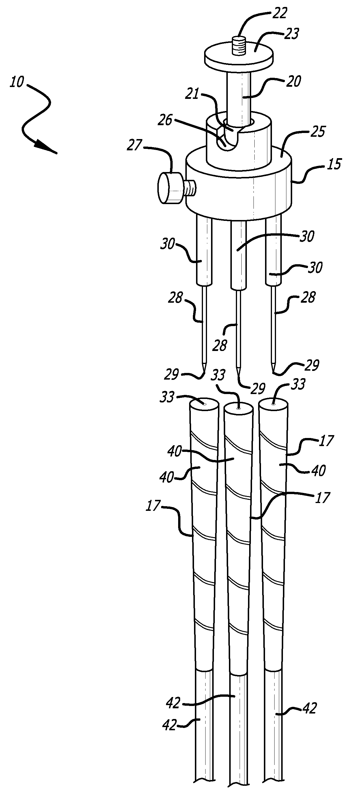
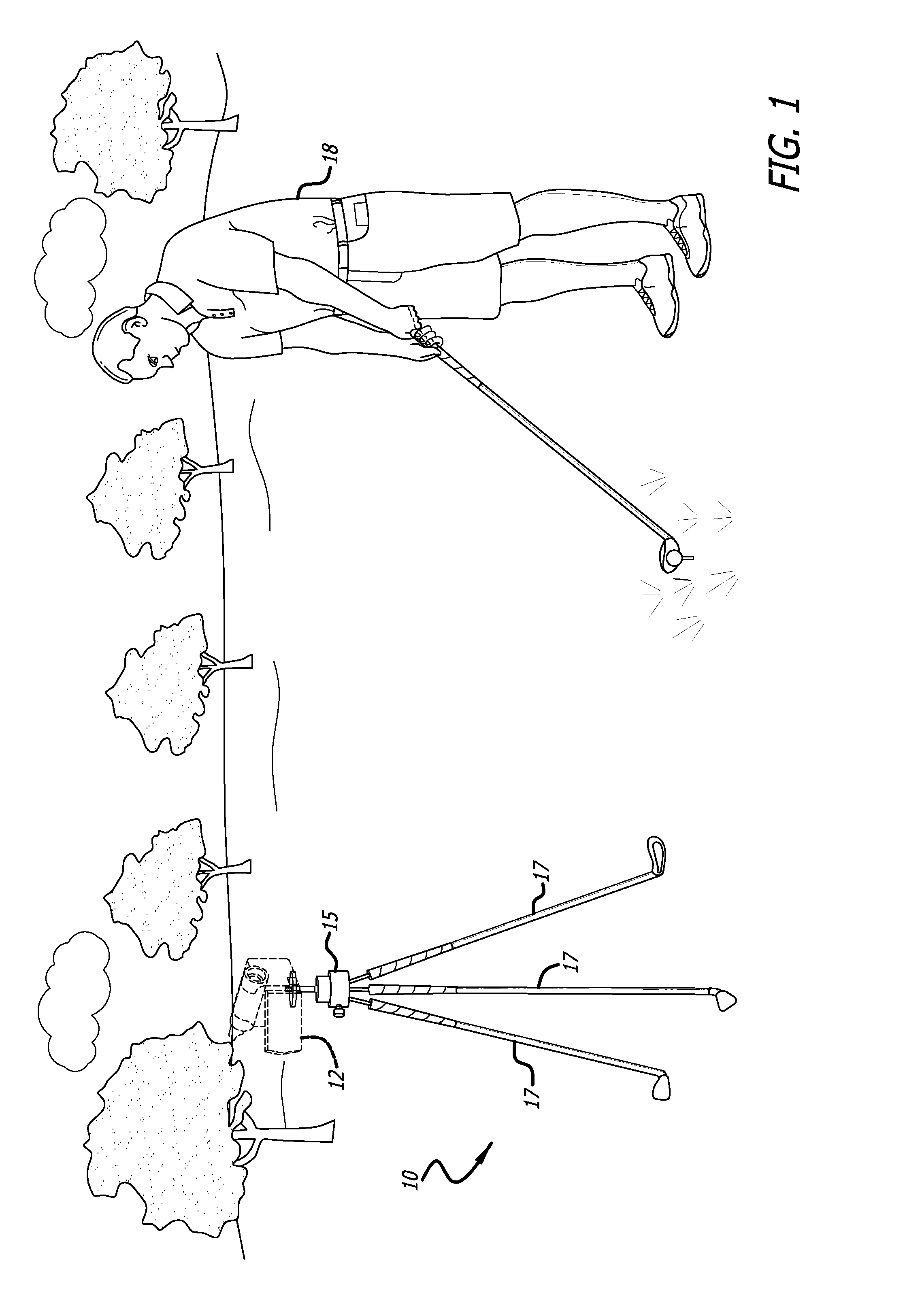
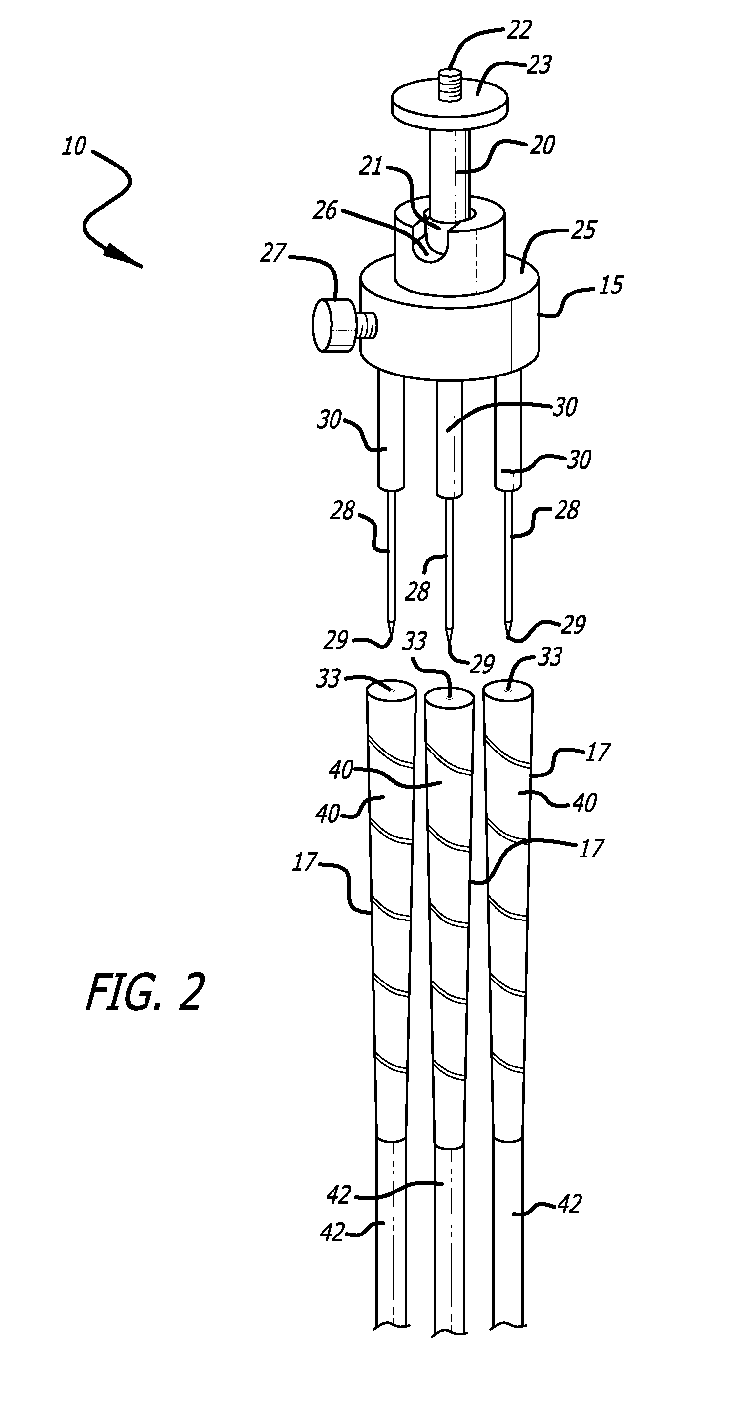
[0015]FIG. 1 illustrates one example of the use of a stand 10, according to a representative embodiment of the present invention. Here, stand 10 is implemented as a tripod for supporting a video-recording device 12, such as a camcorder. However, as will be apparent below, stand 10 also can be used to support a still-image camera, a camera that takes and / or records both still images and video, or any other device. As shown, stand 10 includes a platform assembly 15 and a plurality of golf clubs 17, with the golf clubs 17 constituting most of the length of the legs for stand 10 (three such legs in this embodiment).
[0016]In the present use, video-recording device 12 is used to record the golf swing for a user 18. As described in more detail below, in the preferred embodiments of the invention the user 18 can quickly and easily set up a stand 10 using golf clubs 17 that he or she already has, together with a small platform assembly 15, rather than carrying a much larger camera tripod.
[0...
PUM
 Abstract
Description
Claims
Application Information