
Weft breakage detection device with function of simple setting

A detection device and function technology, applied in textiles, textiles, papermaking, looms, etc., can solve problems such as empty weft phenomenon, lower yield rate of woven products, shortage of weft threads in woven products, etc.

Inactive Publication Date: 2012-07-25
游青榆
View PDF6 Cites 1 Cited by
  • Summary
  • Abstract
  • Description
  • Claims
  • Application Information

AI Technical Summary

Problems solved by technology

[0003] However, the traditional circular knitting machine not only produces empty weft phenomenon due to thread breakage, but also produces empty weft phenomenon when the weft yarn is exhausted. Therefore, as long as the operator fails to detect in time and control the shuttle boat to stop early, the knitted product will be damaged. There are empty weft defects with insufficient weft threads on the surface, which cannot be remedied to form defective products, and the yield rate of woven products is reduced. For this reason, someone invented the weft yarn breakage sensor of the circular spinning machine and the weft yarn breakage sensor of the circular spinning machine Improvements to solve the above problems, wherein, these cases disclose that an induction source is fixed on the ejector of an ejection device, and a sensing device is used to sense the magnetic field generated by the induction source. and achieve the effect of controlling the stop of the shuttle boat; although both previous proposals can achieve the control of the stop of the shuttle boat, because the sensing device is single, the position of the sensing device during setting will often affect the sensing Whether the device is malfunctioning or not, it usually needs to be adjusted and set by a person with considerable experience to avoid the occurrence of malfunctions, let alone an operator who has just come into contact with the weft segment line sensor of the known circular spinning machine, it may It takes a longer time to adjust and set, so the known weft yarn breakage sensor has room and necessity to be improved.

Method used


Image

  • Weft breakage detection device with function of simple setting
  • Weft breakage detection device with function of simple setting
  • Weft breakage detection device with function of simple setting

Examples


Embodiment Construction

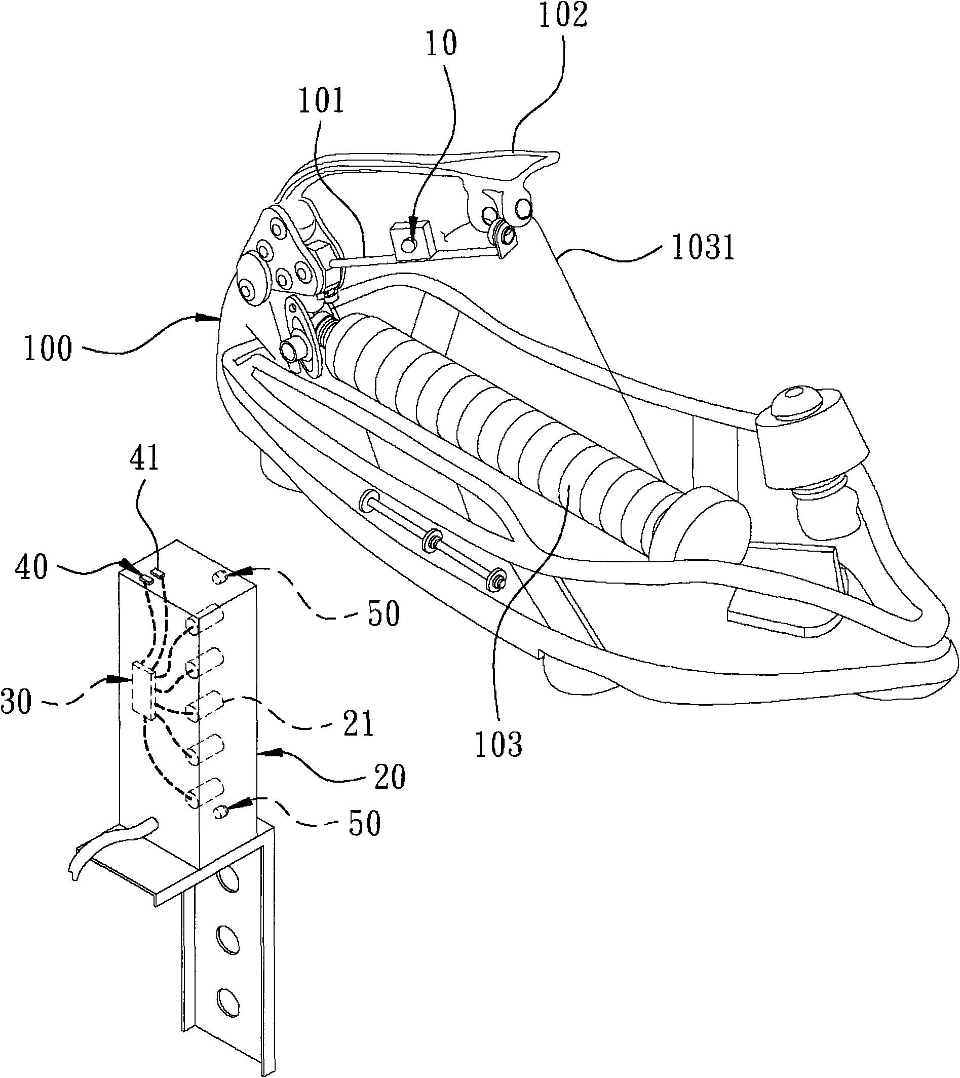
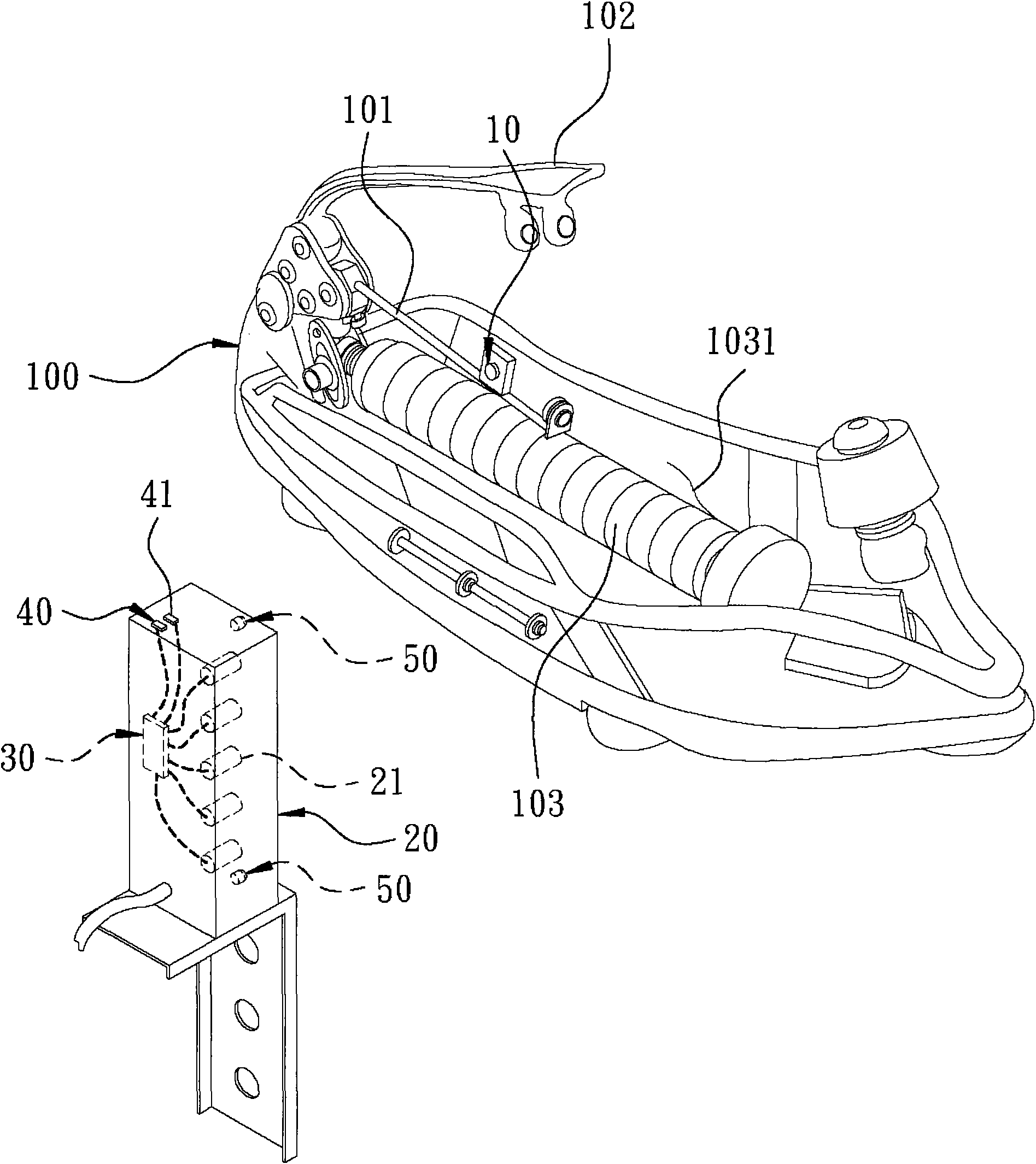
[0022] First, see figure 1 and figure 2 Shown is the schematic diagram of the present invention in the unbroken state of the weft yarn and the schematic diagram of the broken state of the weft yarn; the present invention includes:

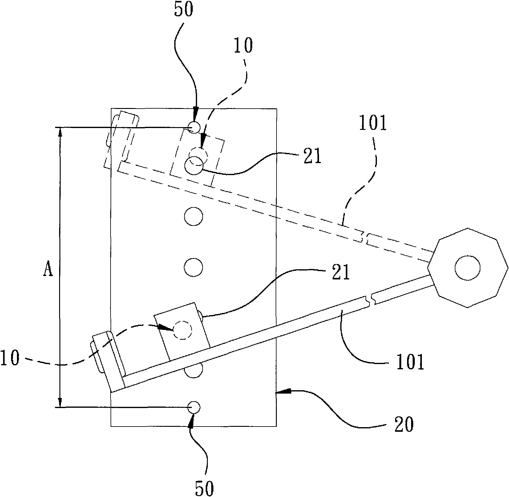
[0023] An induction source 10, in the embodiment of the present invention, the induction source 10 is a permanent magnet, and is installed on a yarn-drawing bar 101 of a shuttle boat 100, and can move with the deflection of the yarn-drawing bar 101, and In the present invention, the shuttle boat 100 is respectively provided with a weft yarn guide rod 102 and a weft yarn bobbin 103, and the weft yarn guide rod 101 can swing between the weft yarn guide rod 102 and the weft yarn bobbin 103, and generally has a first state And a second state, and the first state is the position where the yarn drawing rod 101 is close to the weft yarn guide rod 102 (that is, the yarn drawing rod 101 is pulled by the weft yarn 1031 on the weft yarn bobbin 103), the Th...


PUM


Abstract

A weft breakage detection device with a function of simple setting comprises a sensing source, a sensing unit and a micro-processing unit. The sensing source is mounted on a yarn guide bar of a shuttle and capable of swinging along with the yarn guide rod. The sensing unit comprises at least two sensors disposed at intervals. The sensors are used for respectively sensing the sensing source to generate corresponding signal values. The micro-processing unit is electrically connected with the sensors and capable of receiving the signal values for processing and determination. Therefore, the sensors can be used for automatically sensing the sensing source on the yarn guide bar and transmitting the sensed signal values to the micro-processing unit for determination so as to control the shuttle to stop, the effect of quick and simple setting is achieved, and the time consumed by an operator to make settings is reduced.

Description

technical field [0001] The invention relates to a weft yarn break detection device with simple setting function, which can control the shuttle to stop when the weft yarn breaks, so as to prevent defective products from being produced. Background technique [0002] By the way, most of the lightweight and cheap packaging bags used by ordinary people in daily life are mainly made of PE and PP woven bags, and they are usually made of different sizes of packaging bags by mechanical weaving. Among the machines, the circular knitting machine has many advantages such as fast production, stable quality and convenient use, so it has become the main machine for the industry to make cloth for packaging bags. [0003] However, the traditional circular knitting machine not only produces empty weft phenomenon due to thread breakage, but also produces empty weft phenomenon when the weft yarn is exhausted. Therefore, as long as the operator fails to detect in time and control the shuttle boa...

Claims


Application Information

Patent Timeline
IPC IPC(8): D03D51/40
Inventor 游青榆
Owner 游青榆
Learn More