Tree limb support device

a support device and tree technology, applied in the direction of stand/trestle, kitchen equipment, show hangers, etc., can solve the problems of unsightly guide wires, less healthy and vigorous branches,

Inactive Publication Date: 2009-03-12
BROWN RAYMOND +2
View PDF4 Cites 11 Cited by
  • Summary
  • Abstract
  • Description
  • Claims
  • Application Information

AI Technical Summary

Benefits of technology

[0010]A device for supporting a tree limb, said device comprising a base having top and bottom surfaces for situating said device proximate said tree limb. A telescoping pole is provided having a longitudinal axis and first and second ends, said first end being rotatably secured to said base. A coupling is used for varying the length of said telescoping pole and a support rod is affixed to the second end of said telescoping pole, said support rod being rotatable about said longitudinal axis. Finally, a U-shaped limb support member fixedly appended to said support rod.

Problems solved by technology

As trees age, oftentimes, their branches become less healthy and vigorous and, without suitable intervention, oftentimes would break away from the main trunk of the tree.
Even in situations where a limb is less than vigorous, it is oftentimes desirable to save it rather than to prune or remove it.
It is not uncommon to see braided wire fixed between the limb and load bearing trunk portions of the tree which, although are functional, further provide distress as such braided wire is generally screwed into the bark and limb of the trunk.
Further, such guide wires are often unsightly and prove to be aesthetically detracting from the tree's overall appearance in many instances.

Method used


Image

  • Tree limb support device
  • Tree limb support device
  • Tree limb support device

Examples


Embodiment Construction

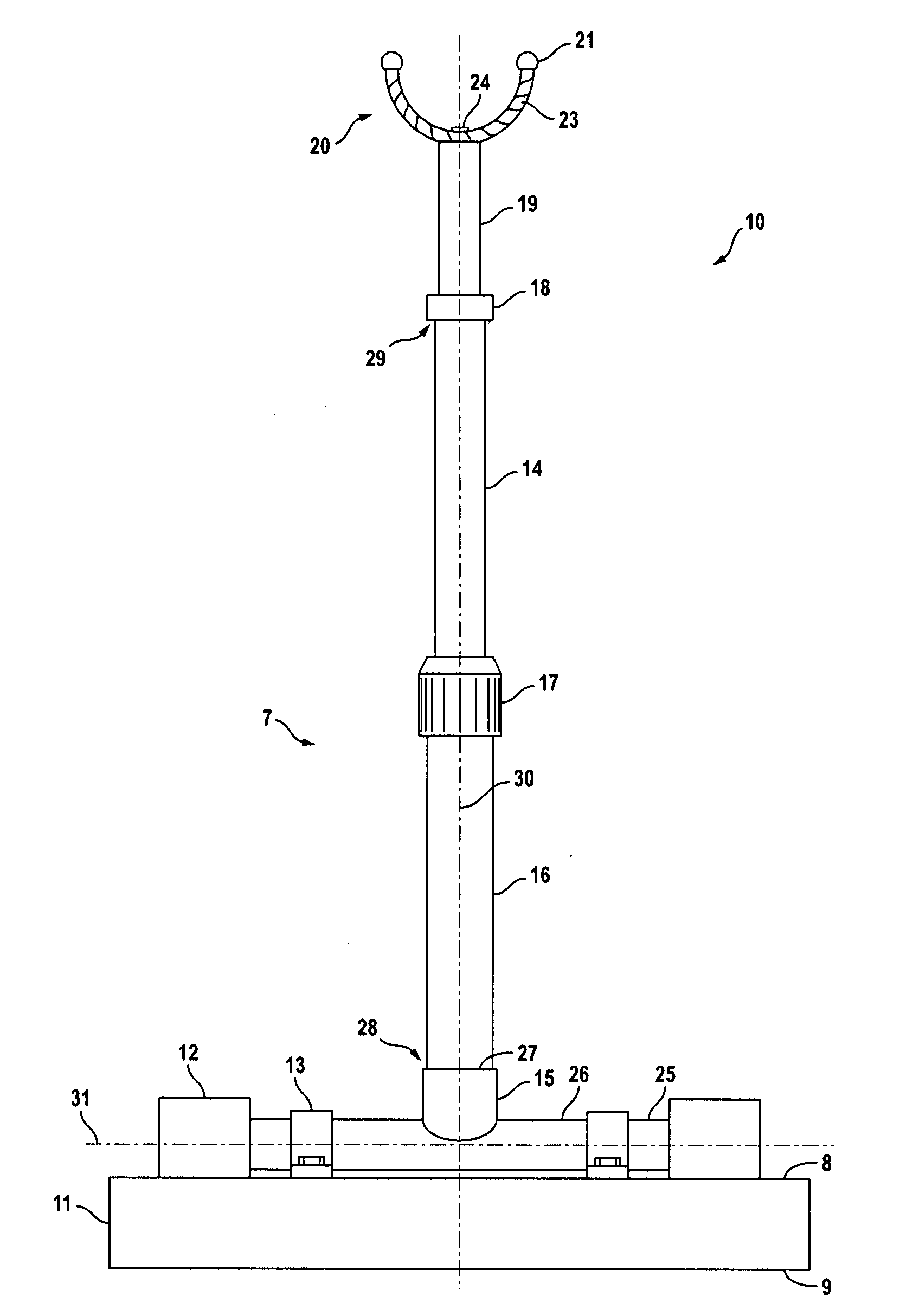
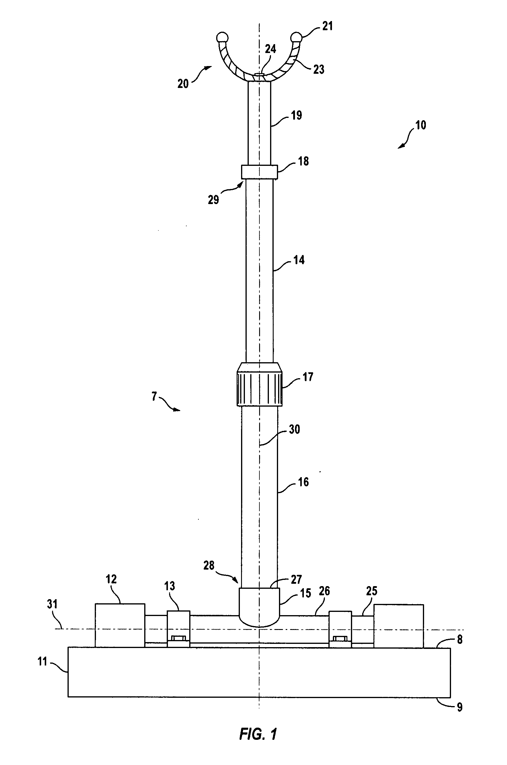
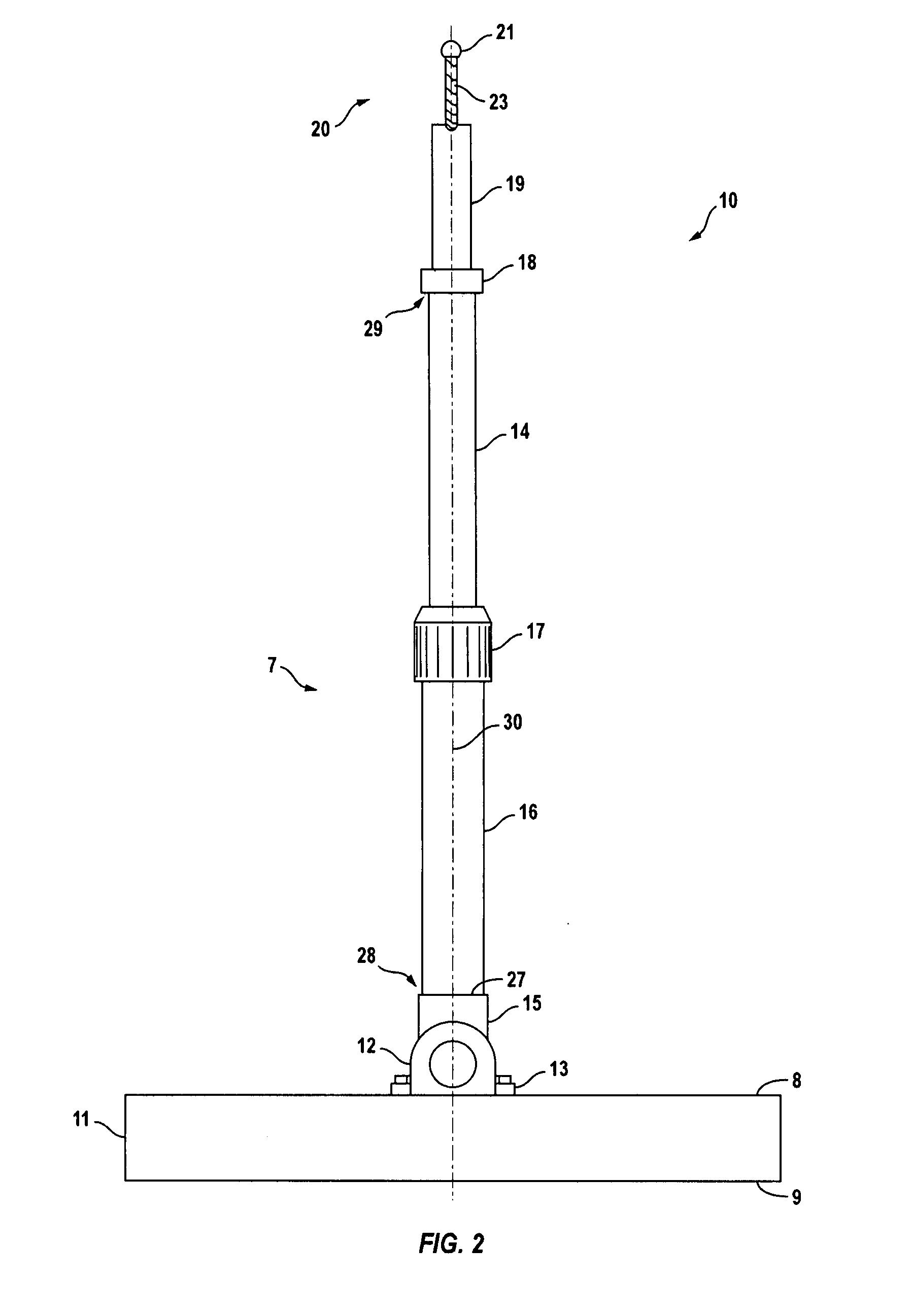
[0013]Turning to FIG. 1, tree limb support device 10 is depicted. The side view of the illustration of FIG. 1 is also referred to as FIG. 2 noting that like reference numerals identify corresponding elements of each figure.

[0014]The present device is intended to reside upon the ground approximate a tree trunk and positioned to support a distressed tree limb. As such, base 11, having top surface 8 and bottom surface 9, the latter to reside upon the ground, constitute a suitable footprint to stabilize the remaining component of the device during use. Because the ground upon which base 11 is to reside is oftentimes uneven, it is contemplated that the telescoping pole 7 having longitudinal axis 30 be rotatably secured to base 11 on top surface 8.

[0015]Base 11 is provided with retaining sleeves 12 and clamp members 13 supporting shaft 25 on either side of longitudinal axis 30. T-shaped sleeve 15 is provided with horizontally extending tubular member 26 for receiving shaft 25 and vertical...


PUM


Abstract

A device for supporting a tree limb. The device includes a base having top and bottom surfaces for situating the device proximate to said tree limb. A telescoping pole having a longitudinal axis and first and second ends is provided, the first end being rotatably secured to the base. A coupling is included for varying the length of the telescoping pole. A support rod is affixed to the second end of the telescoping pole, the support rod being rotatable about the longitudinal axis. A U-shaped limb support member is fixedly appended to the support rod.

Description

TECHNICAL FIELD[0001]The present invention is directed to a device for supporting a tree limb capable of being situated to enable it to appropriately engage the tree limb for proper support.BACKGROUND OF THE INVENTION[0002]As trees age, oftentimes, their branches become less healthy and vigorous and, without suitable intervention, oftentimes would break away from the main trunk of the tree. This can also occur with healthy branches that may be unduly stressed by weight. For example, as fruit develops on the branches of a fruit bearing tree stress is created that the branch or limb must support.[0003]There are many reasons why one may wish to save a tree limb under distress rather than to simply remove it from the main trunk system. If the limb is fruit bearing, the distress would be removed once the fruit is harvested. Even in situations where a limb is less than vigorous, it is oftentimes desirable to save it rather than to prune or remove it. For example, such a limb could aesthet...

Claims


Application Information

Patent Timeline
Patent Type & Authority Applications(United States)
IPC IPC(8): A01G17/10
CPCA01G17/10
Inventor BROWN, RAYMONDBROWN, ROSEBOUDREAU, DIANE
Owner BROWN RAYMOND
Why Eureka
Try Eureka