Die cushion device for press machine

a press machine and cushioning technology, applied in forging presses, forging/pressing/hammering apparatuses, manufacturing tools, etc., can solve the problems of reducing the effective stroke amount at the time of the die cushioning action, reducing the effect of the stroke amount, and ensuring dynamic stability. , the effect of preventing the occurrence of a surge pressur

Active Publication Date: 2009-03-19
AIDA ENG LTD
View PDF9 Cites 36 Cited by
  • Summary
  • Abstract
  • Description
  • Claims
  • Application Information

AI Technical Summary

Benefits of technology

[0040]A die cushion apparatus of a press machine according to a fifteenth aspect of the present invention is in accordance with any one of the first to fourteenth aspects, further comprising a slide speed detector that detects a sliding speed of the press machine or an angular velocity detector that detects an angular velocity of a drive shaft of the press machine, wherein the control device uses a slide speed signal that is detected by the slide speed detector or an angular velocity signal that is detected by the angular velocity detector in compensation for ensuring dynamic stability in die cushion pressure control. 30 According to the present invention, a discharge opening of a fluid hydraulic pump / motor is directly connected to a pressure chamber on a cushion pressure production side of a fluid hydraulic cylinder, and the torque of a rotating shaft of the fluid hydraulic pump / motor is controlled by an electric motor to control the pressure (die cushion pressure) of the pressure chamber on the cushion pressure production side. It is therefore possible to control the die cushion pressure with excellent responsiveness with respect to die cushion pressure commands and to prevent the occurrence of a surge pressure. Further, the die cushion apparatus has excellent energy efficiency because energy that is required for a die cushioning action that a cushion pad receives when die cushioning of the press machine is effected is regenerated as electrical energy through the fluid hydraulic cylinder, fluid hydraulic pump / motor, and electric motor.

Problems solved by technology

The first drawback is that since pressure is generated by squeezing an oil flow, all the energy that is consumed in the die cushioning action is converted to heat.
From an environmental perspective, this can be considered a waste of energy.
The second drawback is that when attempting to control the surge pressure at a collision time after pre-accelerating the cushion pad, there is a problem that the (effective) stroke amount at the time of a die cushion pressure action decreases.
The third drawback is that the die cushion pressure is generated by controlling an oil amount discharged from a pressure chamber on the cushion pressure production side of an oil hydraulic cylinder that is pressed by a press slide (pressure generated using the energy of the press), and is not a pressure that is generated by the die cushion apparatus itself.
Accordingly, it is difficult to maintain pressure in a halt state at the bottom dead center (functional constraint).

Method used


Image

  • Die cushion device for press machine
  • Die cushion device for press machine
  • Die cushion device for press machine

Examples


first embodiment

Control Apparatus (First Embodiment)

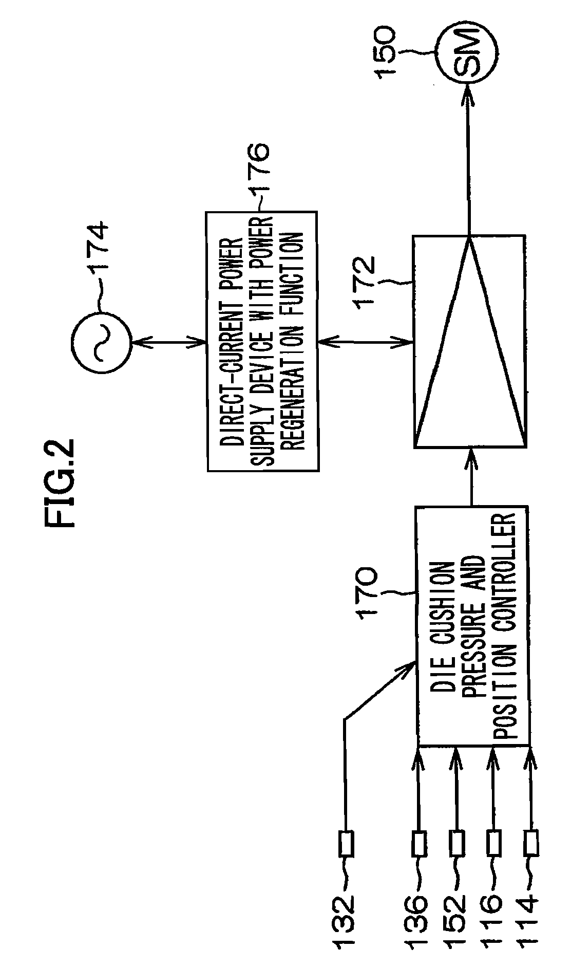
[0123]FIG. 2 is a view that illustrates a first embodiment of a control apparatus in a die cushion apparatus of a press machine according to the present invention. FIG. 2 illustrates a control apparatus that is applied to the die cushion apparatus of the first embodiment.

[0124]This control apparatus chiefly comprises a die cushion pressure and position controller 170, an amplifier and PWM controller 172, an alternating-current power supply 174, and a direct-current power supply device with power regeneration function 176.

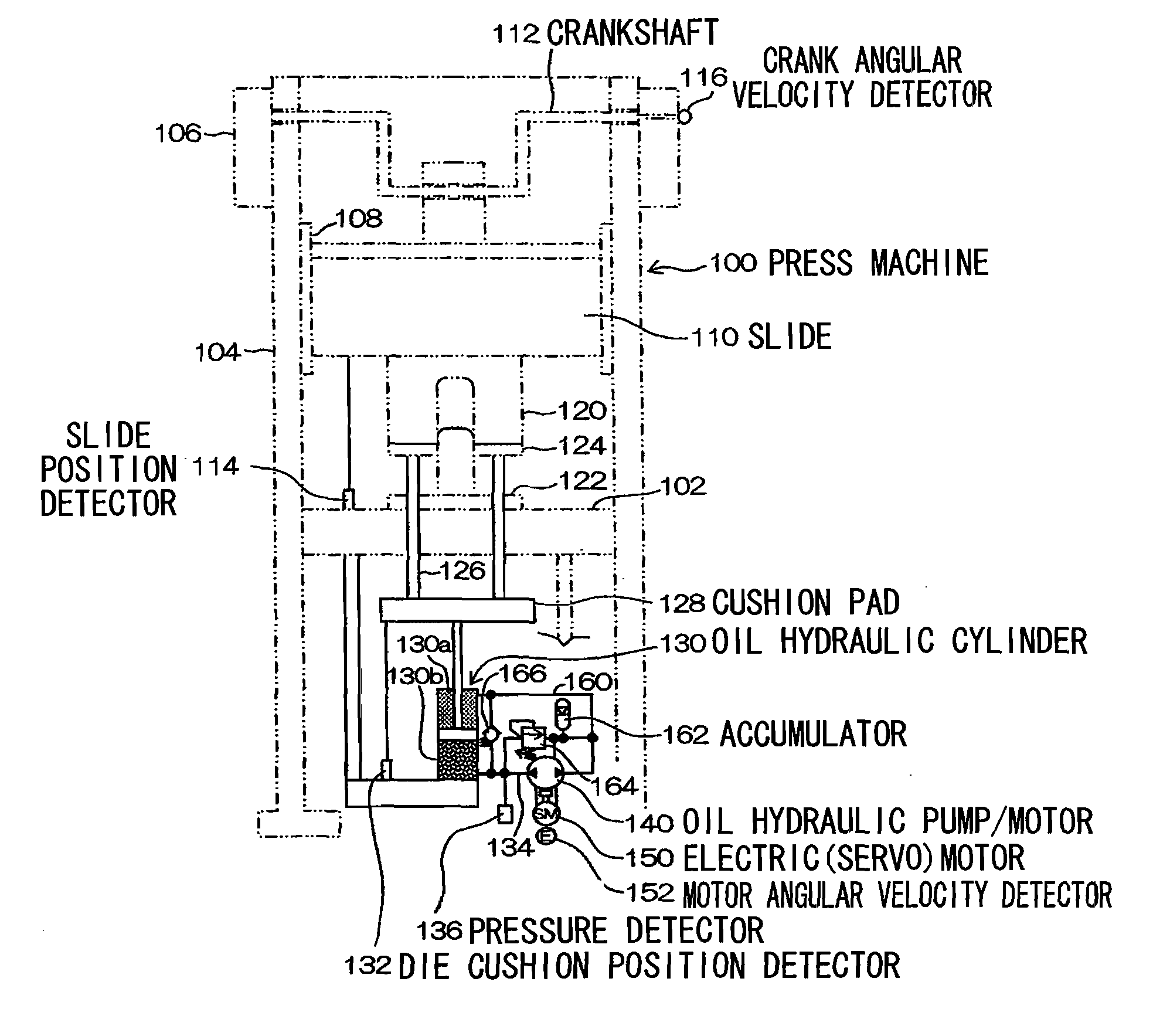
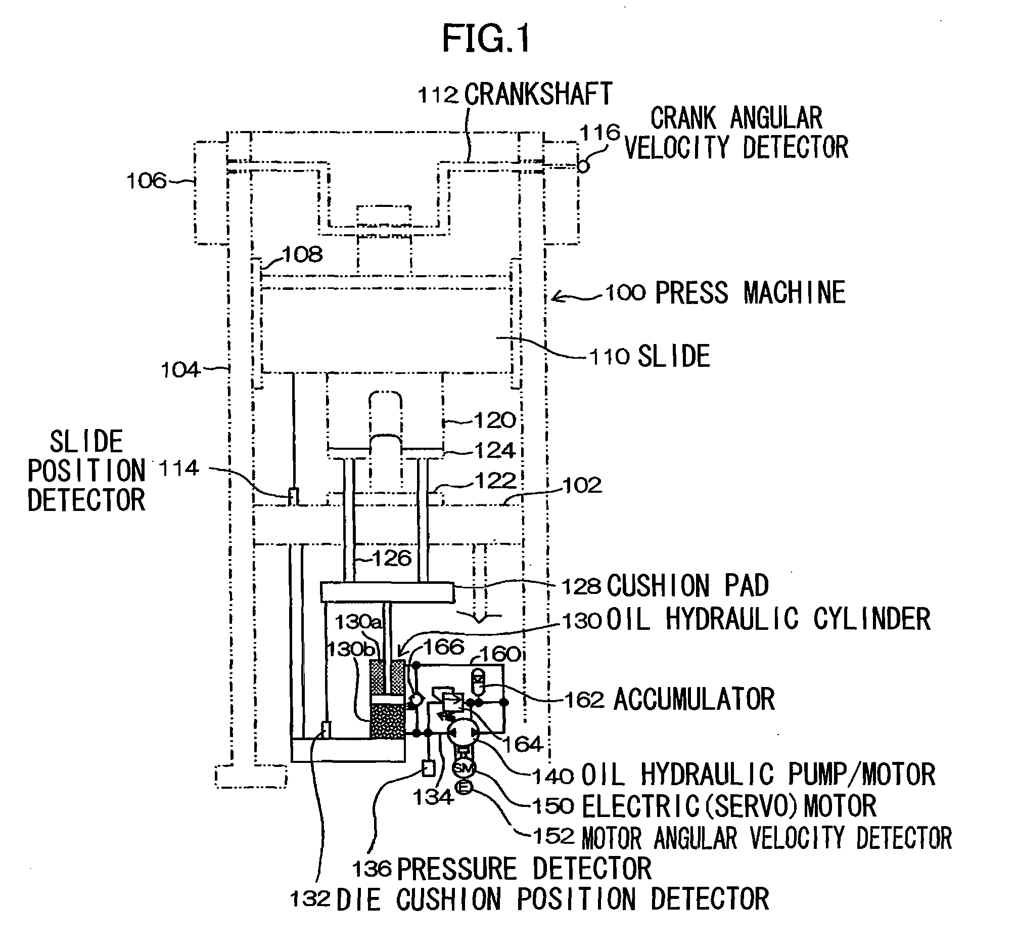
[0125]The die cushion pressure and position controller 170 respectively receives a pressure detection signal indicating a pressure P from the pressure detector 136, an angular velocity signal indicating a motor angular velocity ω from the motor angular velocity detector 152, an angular velocity signal indicating a crank angular velocity from the crank angular velocity detector 116, a position detection signal indicating a slide po...

second embodiment

Control Apparatus (Second Embodiment)

[0145]FIG. 5 is a view that illustrates a second embodiment of a control apparatus for the die cushion apparatus of a press machine according to the present invention. The parts common with parts of the control apparatus according to the first embodiment as illustrated in FIG. 2 are assigned the same reference numerals and detailed explanations thereof are omitted.

[0146]In comparison to the control apparatus according to the first embodiment as illustrated in FIG. 2, the control apparatus according to the second embodiment illustrated in FIG. 5 is different in the respect that a die cushion pressure controller 180 is provided in place of the die cushion pressure and position controller 170.

[0147]The die cushion pressure controller 180 differs from the die cushion pressure and position controller 170 in the respect that a position detection signal from the die cushion position detector 132 is not input to the die cushion pressure controller 180 an...

third embodiment

Control Apparatus (Third Embodiment)

[0149]FIG. 6 is a view that illustrates a third embodiment of a control apparatus for the die cushion apparatus of a press machine according to the present invention. The parts common with parts of the control apparatus according to the second embodiment as illustrated in FIG. 5 are assigned the same reference numerals and detailed explanations thereof are omitted.

[0150]In comparison to the control apparatus according to the second embodiment as illustrated in FIG. 5, the control apparatus according to the third embodiment illustrated in FIG. 6 is different in the respect that a die cushion pressure controller 182 is provided in place of the die cushion pressure controller 180.

[0151]Only a pressure detection signal that is detected by the pressure detector 136 is input to the die cushion pressure controller 182.

[0152]The die cushion pressure controller 182 conducts die cushion pressure control by outputting a torque command value that is calculate...


PUM

PropertyMeasurementUnit
pressureaaaaaaaaaa
electrical energyaaaaaaaaaa
angular velocity detectoraaaaaaaaaa

Abstract

A die cushion apparatus of a press machine in which a discharge opening of a fluid hydraulic pump/motor is directly connected to a pressure chamber on a cushion pressure production side of a fluid hydraulic cylinder and the torque of a rotating shaft of the fluid hydraulic pump/motor is controlled by an electric motor to control a pressure (die cushion pressure) of the pressure chamber on the cushion pressure production side. It is therefore possible to control the die cushion pressure with excellent responsiveness with respect to a die cushion pressure command and prevent occurrence of a surge pressure. The die cushion apparatus also has excellent energy efficiency since energy required for a die cushioning action that a cushion pad receives when effecting die cushioning of a press machine is regenerated as electrical energy through the fluid hydraulic cylinder, fluid hydraulic pump/motor, and electric motor.

Description

TECHNICAL FIELD[0001]The present invention relates to a die cushion apparatus of a press machine, and more particularly to technology that enables control of a surge pressure and servo control of a die cushion pressure at the start of press forming by a press machine.BACKGROUND ART(a) Pneumatic Die Cushion Apparatus[0002]A pneumatic die cushion apparatus is constructed by connecting a pneumatic cylinder that supports a cushion pad and a steel cylinder in which a low pneumatic pressure is accumulated. A pneumatic die cushion apparatus has advantages including convenience and that fact that a surge pressure does not occur since it uses a compressible fluid.[0003]On the other hand, there are disadvantages such as a problem that the size of the apparatus increases due to the need to provide a pit accompanying upsizing of pneumatic cylinders, performance problems such as vibrations upon collision accompanying pressure fluctuations in the compressible fluid or dumping deficiencies, and a ...

Claims


Application Information

Patent Timeline
Patent Type & Authority Applications(United States)
IPC IPC(8): B21D22/00
CPCB21D24/02F15B2211/88B21D24/14F15B2211/20515F15B2211/20561F15B2211/20576F15B2211/212F15B2211/27F15B2211/6309F15B2211/633F15B2211/6336F15B2211/6651F15B2211/6653F15B2211/7107F15B2211/76B21D24/08Y02P70/10B21D24/00B30B15/00
Inventor KOHNO, YASUYUKISOMUKAWA, MINORU
Owner AIDA ENG LTD
Why Eureka
Try Eureka