Explosion containment vessel

a technology for containment vessels and explosives, applied in the direction of insulated conductors, coupling device connections, cables, etc., can solve problems such as sparks that may ignite chemicals in the environmen

Inactive Publication Date: 2009-03-19
BARKSDALE
View PDF5 Cites 4 Cited by
  • Summary
  • Abstract
  • Description
  • Claims
  • Application Information

AI Technical Summary

Benefits of technology

[0005]The bore section that the tubular seal seals to, and the corresponding seal section that lies therein, are tapered to be of progressively smaller diameters at progressively more forward locations therealong. As a result, when the tubular seal is pressed forward deeper into the tapered bore section, the seal is compressed and its material seals tightly to the bore walls and to the cable. The tapered end of the bore has a stop that limits forward movement of the front end of the tubular seal. When the seal abuts the stop, further turning of the nut causes further expansion of the seal.

Problems solved by technology

This gives rise to the danger that when switches operate, they can create sparks that may ignite chemicals in the environment.

Method used


Image

  • Explosion containment vessel
  • Explosion containment vessel
  • Explosion containment vessel

Examples


Embodiment Construction

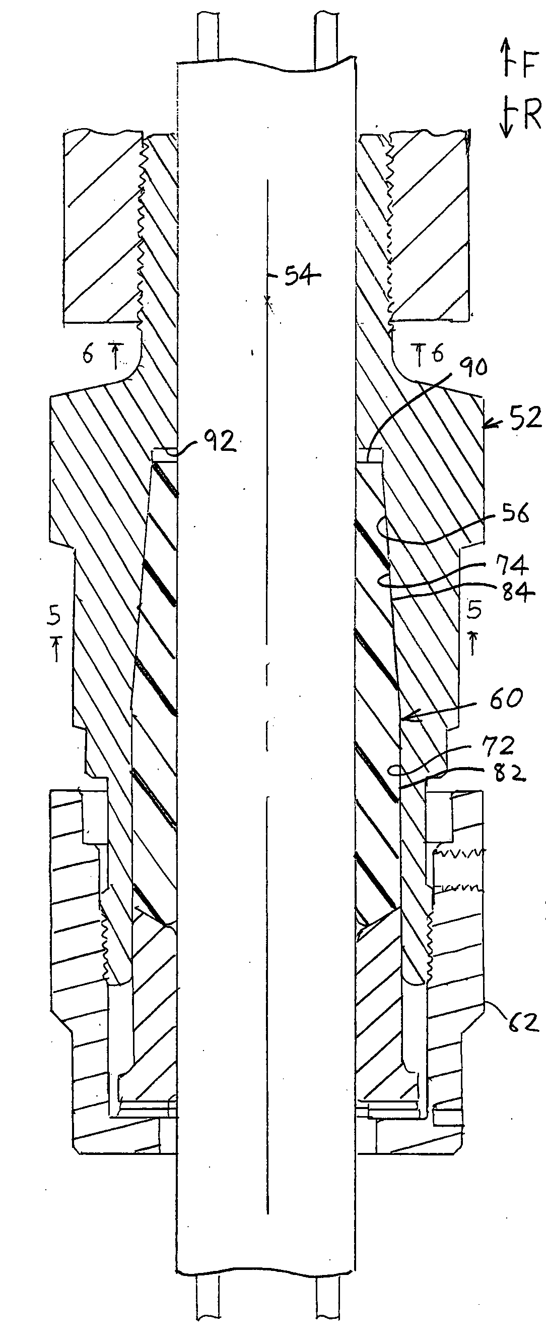
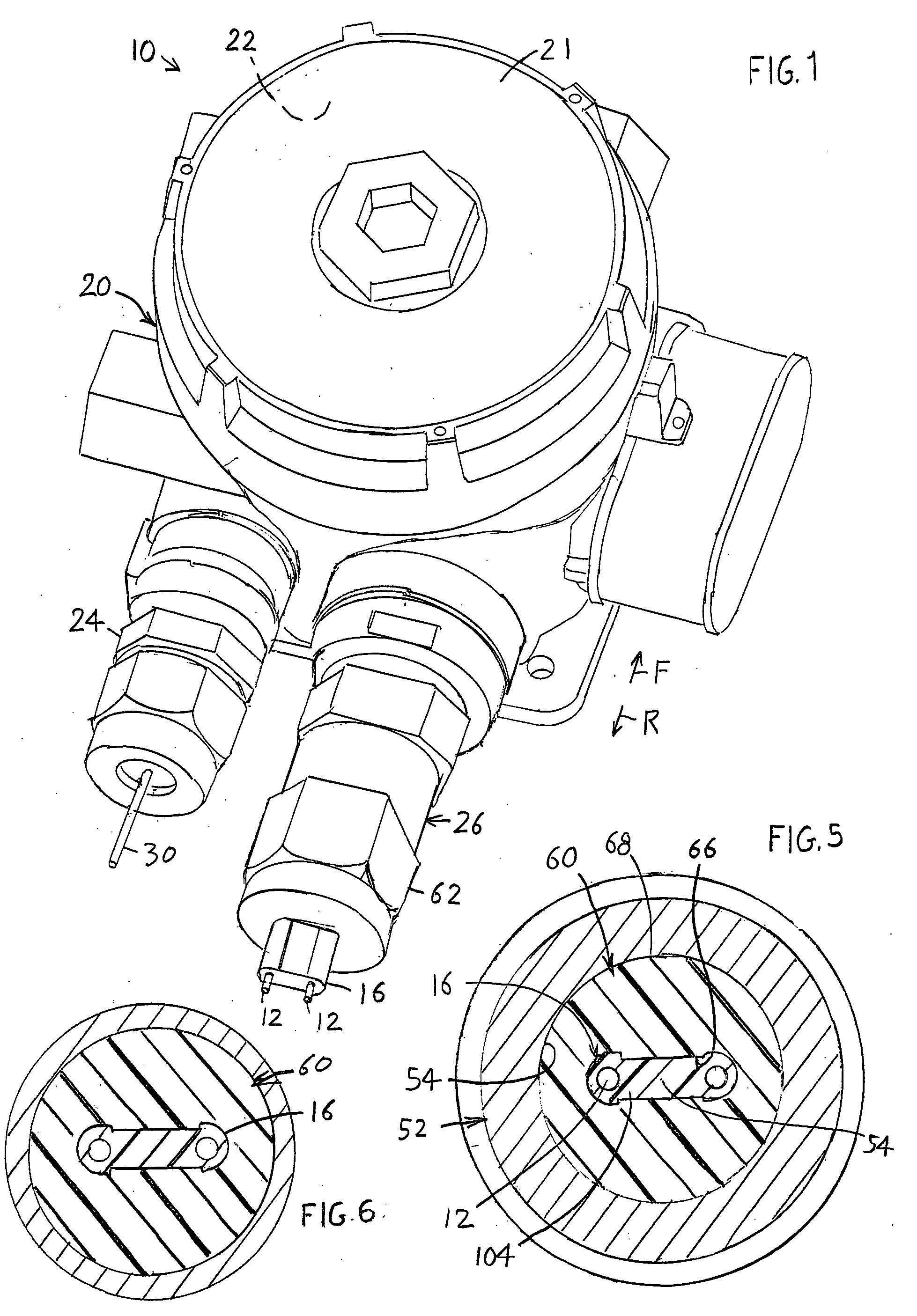
[0013]FIG. 1 shows an explosion proof containment vessel 10 that holds switches that control the flow of electrical current through conductors 12 of a flat cable 16. The cable 16 extends to an electrically energized heater (not shown) to energize it to heat chemicals when their temperature reaches the lower end of a desired range of temperatures and to stop energizing the heater when the temperature reaches the higher end of the range. The vessel includes a housing 20 with a cover 21 and a cavity 22, and a pair of projections 24, 26 that project rearward R from the housing. The cable-guiding projection 26 surrounds the flat cable 16. The tube-guiding projection 24 surrounds a tube 30 that carries a fluid that is at about the same temperature as the chemicals whose temperature is to be maintained within the desired range.

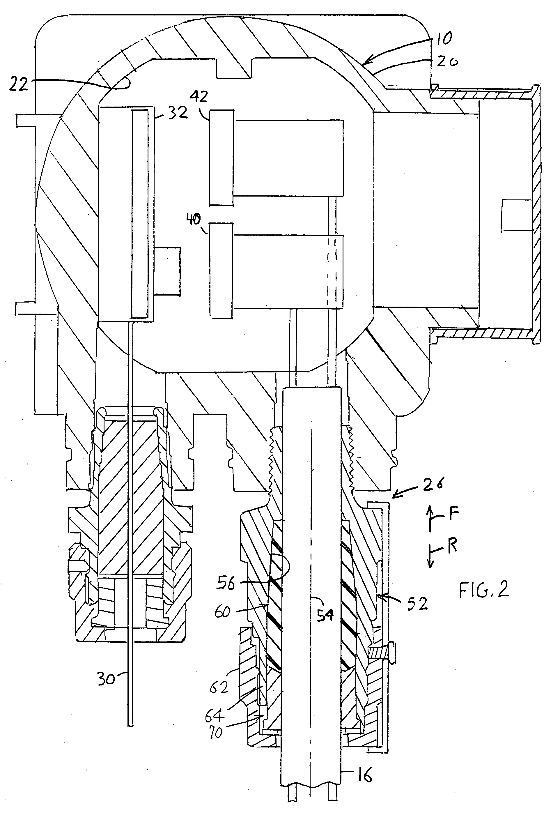
[0014]FIG. 2 shows that the vessel encloses a temperature-sensing actuator 32 and a pair of switches 40, 42 that are operated by the actuator so the switches are ope...


PUM


Abstract

An enclosure (10) that contains a switch (40, 42) and that is surrounded by an explosive or flammable environment that could be ignited by a spark from the switch, includes a body (52) that guides a flat cable (16) through a body bore (56) to the inside of the vessel. A tight and strong seal is formed around the flat cable by a tubular seal (60) that lies in the body bore, that is formed of Teflon, and that has a tapered seal section (84) that lies in a tapered section (74) of the bore. A nut (62) at the rear of the body can be turned to push the tubular seal forward within the body bore and thereby compress it against the outside of the flat cable to form an explosion-proof seal.

Description

BACKGROUND OF THE INVENTION[0001]Industrial plants that process volatile (explosive or flammable) chemicals such as gaseous hydrocarbons, often maintain the chemicals at a predetermined temperature by heating them with currents passing through a flat self-regulating heating cable. A pipe carries fluid at the same temperature as the chemicals being processed, to an explosion containment vessel that contains one or more switches that are closed and opened according to the temperature of fluid in the tube. This gives rise to the danger that when switches operate, they can create sparks that may ignite chemicals in the environment. Sometimes the containment vessel is opened for maintenance etc. and the volatile environment drifts into the explosion containment vessel, where it can ignite when the next spark is generated. The purpose of the containment vessel is to prevent the flame or explosion that occurs inside the vessel, from passing out of the vessel into the volatile environment.[...

Claims


Application Information

Patent Timeline
Patent Type & Authority Applications(United States)
IPC IPC(8): H02G3/18
CPCH01H1/58H01H9/042H02G3/22H01R13/59H02G3/088H01R13/527
Inventor KIM, YONG C.
Owner BARKSDALE
Why Eureka
Try Eureka