
Apparatus and method for separating a stack of sheets from a pile of sheets

Active Publication Date: 2009-03-19
ALLIANCE MACHINE SYST INTENAT
View PDF23 Cites 6 Cited by
  • Summary
  • Abstract
  • Description
  • Claims
  • Application Information

AI Technical Summary

Benefits of technology

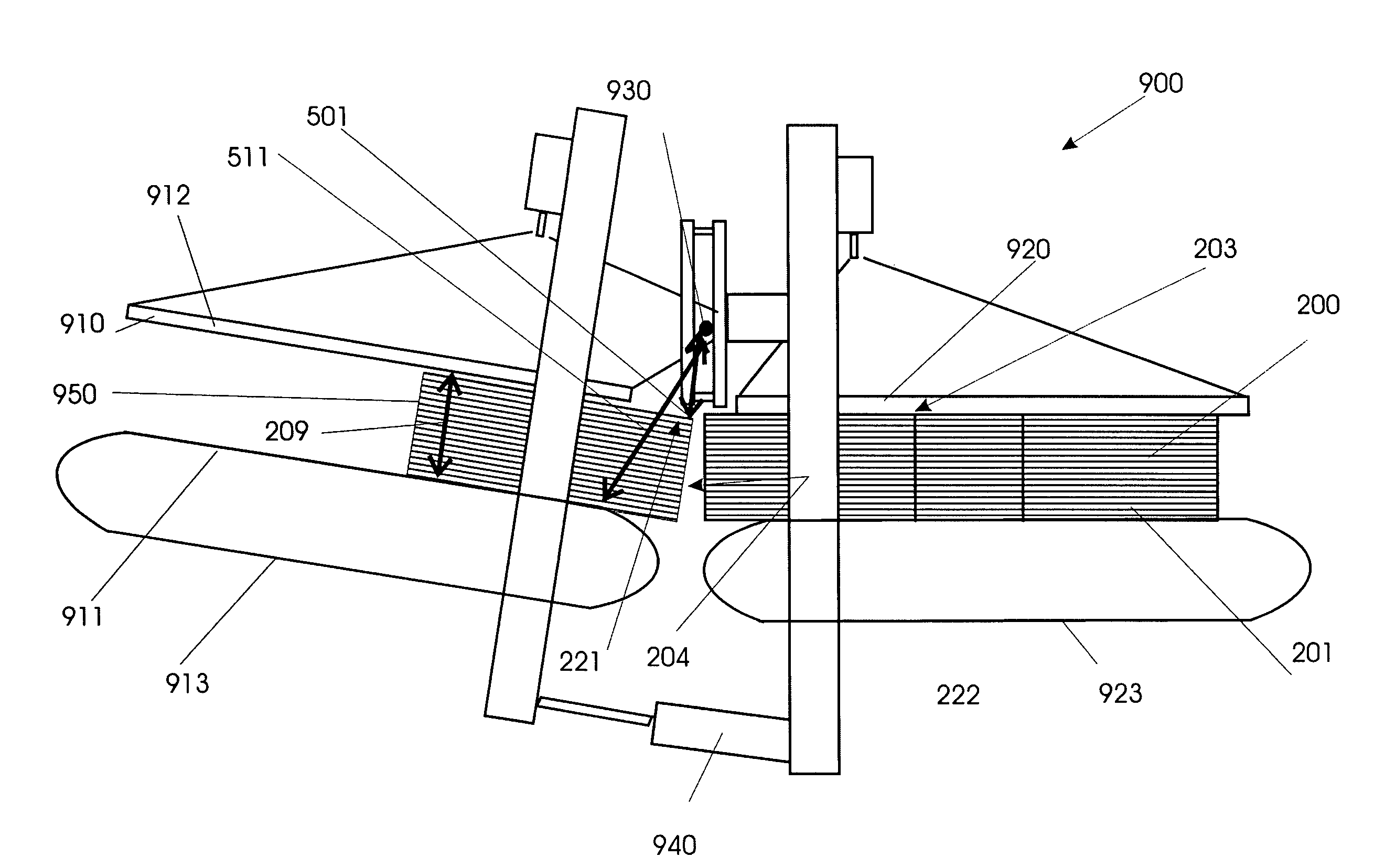
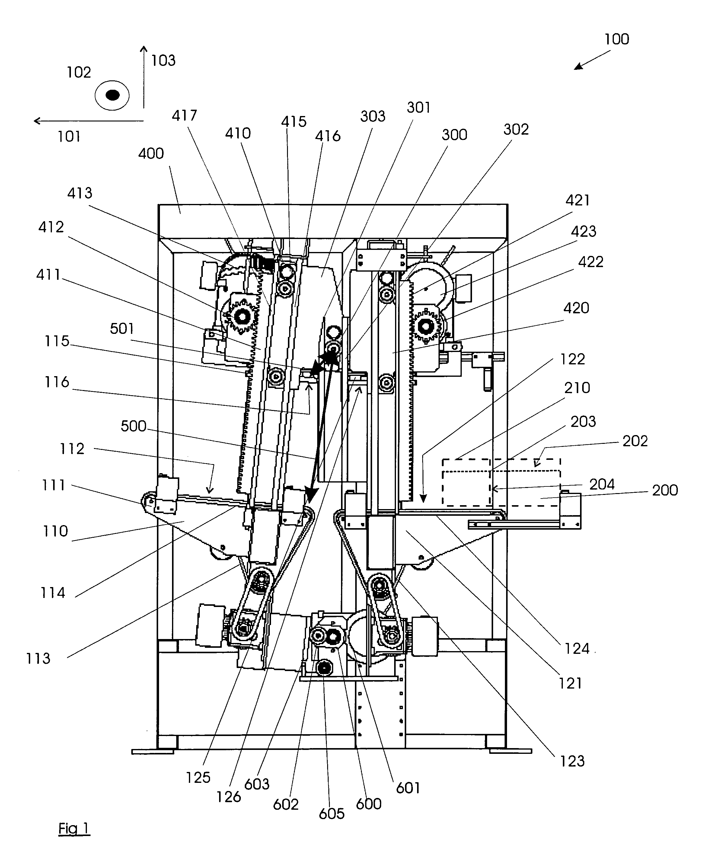
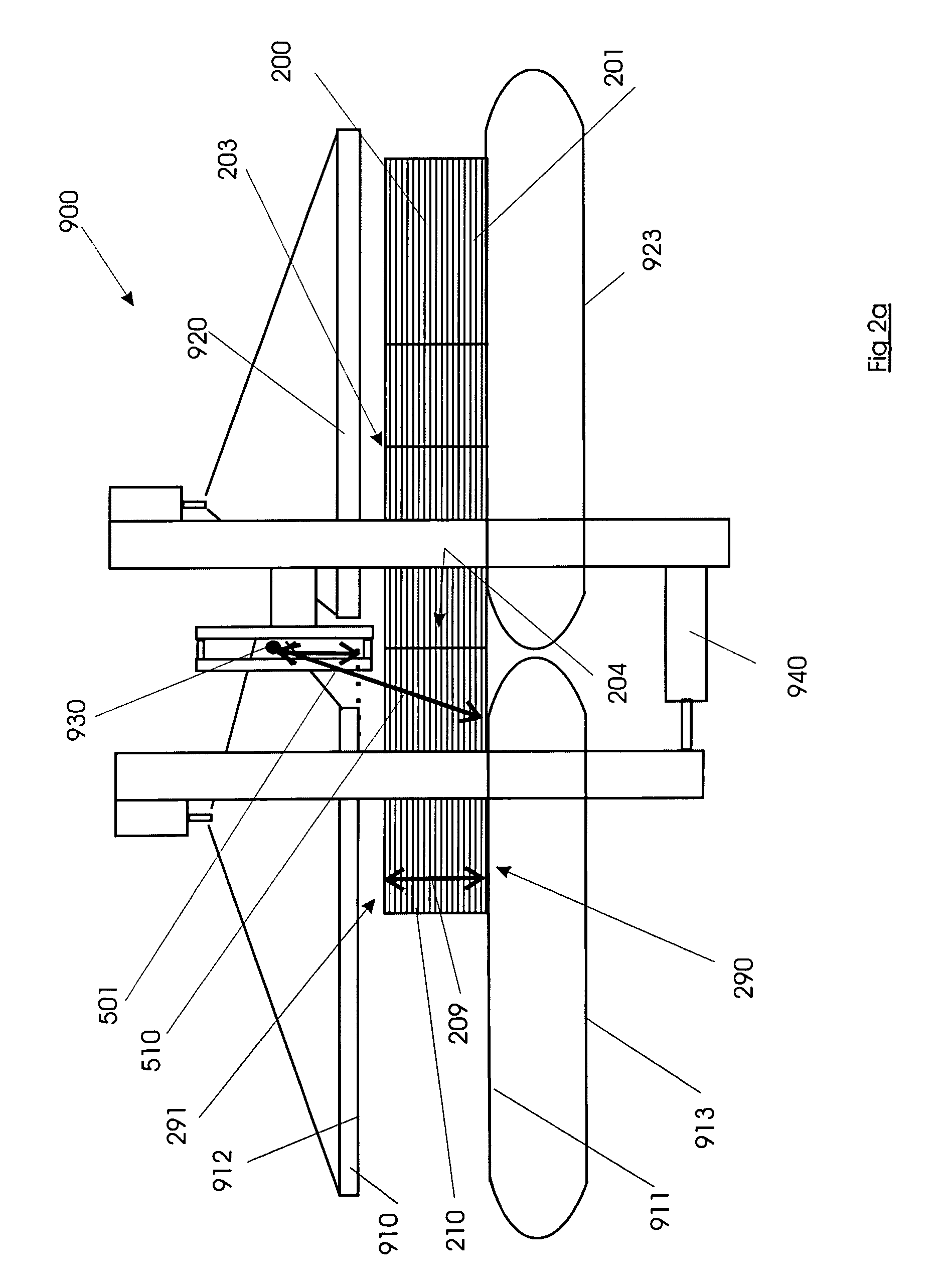
[0021]The first clamp is rotatable relative to the second clamp about an axis. The rotation of the first clamp relative to the second clamp brings about the separation of a stack of sheets from the pile of sheet material by breaking tear paths present in the tear surface The at least one contact point is located between the axis and the sustaining surface and the first clamp is adapted to change between opened and closed conditions. The first clamp in the closed condition holds the pile in a position fixed relative to the sustaining point, the first clamp in the opened condition allowing the pile to move relative to the sustaining point. The distance between axis and sustaining point is adjustable during operation of the apparatus in function of the height of the pile.
[0022]The distance between plates moving downwards to press the pile to the support (under which the axis is present) changes during operation. The axis is displaced relative to a sustaining point, hence this point is located under the pile on order to be able to support the pile. Hence the sustaining point is be the lower of the two parts of the elements of the clamp. The term sustaining also makes clear how the first clamp, thus also the axis is positioned relative to the vertical. The clamp is to be understood closed when the pile or stack is fixed in between the contacting point and the sustaining point. It is not necessarily the position where the contacting and sustaining point meet (no product present in the clamp). The clamp is to be understood opened when no pile or stack is fixed in between the contacting point and the sustaining point. It is not necessarily the position for which the distance between the contacting and sustaining point is brought to its maximum.
[0023]Optionally, the distance between the axis and the sustaining point may be adjusted during operation of the apparatus, while providing the axis at a height difference of 8 cm to 15 cm above the contacting point, optionally at a height difference in the range of 10 cm to 15 cm, such as in the range of 10 cm to 12 cm,. The height difference is measured in a direction perpendicular to the surface of the sheets of the pile.
[0024]Some embodiments of apparatus according to the first aspect of the invention have as an advantage that, in

Problems solved by technology

This causes the tear lines to break by e.g. causing rupture of the nicks of the pre-cut lines.
If sheets with a high breaking strength in a direction parallel to the sheet surface are to be broken, excessive forces are needed to move the clamps sidewise.
These high clamping forces applied to the pile of sheets can damage the sheets positioned near the upper and lower side of the pile, i.e. near the clamps.
Stacks, which are not clamped during moving of the clamps, may become misaligned by mutually displacing sheets within this unclamped stack.
This however causes larger machine elements, e.g. la

Method used


Image

  • Apparatus and method for separating a stack of sheets from a pile of sheets
  • Apparatus and method for separating a stack of sheets from a pile of sheets
  • Apparatus and method for separating a stack of sheets from a pile of sheets

Examples


Embodiment Construction

[0054]The present invention will be described with respect to particular embodiments and with reference to certain drawings but the invention is not limited thereto but only by the claims. The drawings described are only schematic and are non-limiting. In the drawings, the size of some of the elements may be exaggerated and not drawn on scale for illustrative purposes. The dimensions and the relative dimensions do not correspond to actual reductions to practice of the invention.

[0055]Furthermore, the terms first, second, third and the like in the description and in the claims, are used for distinguishing between similar elements and not necessarily for describing a sequence, either temporally, spatially, in ranking or in any other manner. It is to be understood that the terms so used are interchangeable under appropriate circumstances and that the embodiments of the invention described herein are capable of operation in other sequences than described or illustrated herein.

[0056]More...


PUM


Abstract

Apparatus for separating a stack of sheets from a pile of sheet material that is arranged so that tear paths of a plurality of sheets form a tear surface includes a first clamp for clamping the pile at a first side of the tear surface and a second clamp for clamping the pile at a second side of the tear surface. At least the first clamp includes a sustaining member having at least one sustaining point for supporting the pile, and an upper member having at least one contact point for contacting the pile. Rotation of the first clamp relative to the second clamp brings about the separation of a stack of sheets from the pile of sheet material by breaking the tear paths present in the tear surface.

Description

TECHNICAL FIELD OF THE INVENTION[0001]The present invention relates to methods and apparatus for separating a stack of sheet material from a pile of sheet materials, which separation is achieved by breaking tear paths or tear lines present in the surfaces of a plurality of stacked sheets.BACKGROUND OF THE INVENTION[0002]Apparatus for separating or breaking a pile of sheets, such as piles of cardboard or paper sheets, into stacks of sheets are known in the art.[0003]There are at least three main types of apparatus for separating a pile of sheets into stacks of sheets according to a tear surface, which tear surface is constituted by tear paths, usually coplanar tear lines, each sheet in the pile of sheets being provided with at least one tear path along its surface. The tear path may be e.g. a pre-cut line, comprising nicks alternating with notches along the line.[0004]The first type of apparatus comprises at least a first clamp for clamping the pile at a first side of the tear surfac...

Claims


Application Information

Patent Timeline
IPC IPC(8): B26F3/02
CPCB26D7/0675B26F2210/02B26F3/002Y10T225/10Y10T225/325Y10T225/357
Inventor JANS, RENE
Owner ALLIANCE MACHINE SYST INTENAT
Learn More